Do you have a question about the LS ELECTRIC H100 Series and is the answer not in the manual?
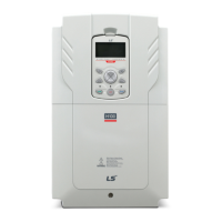
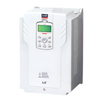
Details the user-friendly keypad for commands, configuration, and monitoring.
Highlights the built-in EMC filter for noise reduction and global compliance standards.
Covers communication modules like RS-485/BACnet and exclusive software features.
Explains power-free operation, LED feedback, parameter read/write, and easy installation.
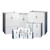
Details size reduction by 34% and side-by-side installation capability.
Describes soft fill, start/end ramp, and dec valve ramp operations for pump control.
Covers multi-motor control, real-time clock scheduling, and flow compensation.
Details pump clean, PID compensation, load tuning, and fire mode operations.
Explains auto torque boost, lubrication, damper, level, and pipe broken detection.
Lists motor ratings and specifications for 3-Phase 200V and 400V models.
Details control modes, frequency settings, and operational functions.
Covers protective functions, ambient conditions, and operational environment.
Details wiring for multifunctional inputs and analog settings.
Details wiring for analog output, communication, and relay outputs.
Details power terminal marks and connections for 0.75-90kW models.
Details power terminal marks and connections for 110-500kW models.
Details input terminal marks for 5.5-90kW and 110-500kW models.
Details analog output terminals and pulse output terminal.
Details terminals for abnormal signals, relays, and RS-485 input.
Specifies wire gauge (AWG) and screw size for wiring.
Details terminal screw size and torque for input/output and control circuits.
Covers jump code, target frequency, run direction, accel/decel times.
Details jog frequency, acceleration/deceleration, and motor capacity settings.
Covers auxiliary command, second frequency, and V/F pattern settings.
Details motor pole, current, voltage, efficiency, and power display settings.
Covers acceleration/deceleration patterns, start/stop modes, and direction control.
Details DC braking settings and frequency limit/jump configurations.
Covers carrier frequency, switching mode, and hunting prevention settings.
Details speed search, energy buffering, and torque boost parameters.
Details V1/V2 analog input polarity, filter, voltage, and rotation direction settings.
Details I2 current input filter, minimum/maximum current, and rotation direction settings.
Details function settings for multifunctional input terminals P1-P7.
Details analog output terminals and pulse output terminal.
Details terminals for abnormal signals, relays, and RS-485 input.
Covers analog output 1 & 2 item, gain, bias, filter, and constant settings.
Details trip output item and multifunction relay 1 item configurations.
Covers drive ID, protocol, speed, frame settings, and field bus speed.
Details output and input communication number settings.
Covers PID function selection and various PID monitors.
Details PID reference 1 source, keypad, auxiliary source, mode, and gain.
Details PID reference 2 source, keypad, and auxiliary source settings.
Covers EPID1 mode selection and command source selection.
Details EPID1 P-Gain, I-Time, D-Time, feedforward gain, and output filter.
Covers EPID1 output high/low limits, inversion, unit, scale, and percentage settings.
Details sleep boost level/speed and PID sleep/wake time/frequency settings.
Covers MMC function, bypass selection, and auxiliary motor settings.
Details start and stop frequencies for auxiliary motors.
Covers load curve tuning, frequency settings, current, and power parameters.
Details pump clean settings, operation delay, acceleration, and deceleration times.
Covers current date, time, weekday, and date format settings.
Details summer time start/end dates and time period settings.
Covers settings for exception dates 1 through 8.
Details 1/0 open phase protection, trip deceleration, and auto retry settings.
Covers overload warning/trip and under-load warning/trip protections.
Details fire mode settings and stall prevention/level configurations.
Covers 2nd motor acceleration, deceleration, and capacity settings.
Details 2nd motor stall prevention and overheat prevention parameters.
Details trip modes and general configuration settings.
Covers keypad language, display settings, and parameter initialization.
Lists parameters for Compressor (MC1) and Supply Fan (MC2) macro groups.
Lists parameters for Exhaust Fan (MC3) and Cooling Tower (MC4) macro groups.
Lists parameters for Vacuum Pump (MC6) and Constant Torque (MC7) macro groups.
Provides dimensional data for IP20 type drives.
Provides dimensional data for IP00 type drives.
Details dimensions for drives with flange attachment and flange mounting.
Details dimensions for drives with conduit attachment and conduit mounting.
Details current and inductance specs for AC input fuses and reactors.
Details current and inductance specs for DC reactors.
Specifies MCCB, ELCB, and MC models and ratings for peripheral devices.
Details UL/Non-UL types of DB units and their terminal arrangements.
Provides terminal connection diagrams for DB units and resistors.
Details resistor specs based on torque and wattage ratings.
Illustrates basic wiring diagrams for DB units and resistors.
| Brand | LS ELECTRIC |
|---|---|
| Model | H100 Series |
| Category | DC Drives |
| Language | English |