Do you have a question about the LS ELECTRIC H100 2(PLUS) Series and is the answer not in the manual?
Details on how to identify the H100+ inverter based on capacity and power source specifications on the rating plate.
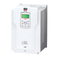
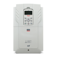
Illustration and identification of various parts of the inverter, with details that may vary between product groups.
Details on ideal operation and installation conditions for the inverter, including ambient temperature, humidity, and altitude.
Guidelines for choosing an installation location, considering weight support, vibration, and air circulation for optimal performance.
Information and specifications for selecting appropriate power and signal cables for safe and reliable operation of the product.
Procedures for mounting the inverter on a wall or inside a panel, ensuring sufficient space and proper alignment.
Instructions to remove the protective insulation strip and enable the inverter's built-in Real-Time Clock battery.
Detailed information on connecting power and control terminal blocks, including warnings and circuit specifications.
Instructions to disable the built-in EMC filter for power sources with asymmetrical grounding connections.
Steps to test the inverter after installation, including power supply, command source, frequency reference, and motor rotation checks.
Description of the keypad layout, including display and operation keys, and their respective functions.
Explanation of the inverter's operable modes (HAND, AUTO, OFF) and how to switch between them.
Guidance on monitoring faults during inverter operation, including viewing fault trip information and history.
Procedure to revert all parameter settings back to factory defaults, either for the entire inverter or specific groups.
Details on parameters related to drive functions, including jump code, target frequency, and acceleration/deceleration times.
Parameters for basic functions like jump code, auxiliary reference source, and motor settings.
Parameters for advanced functions such as acceleration patterns, stop modes, and DC braking.
Parameters related to control functions like carrier frequency, switching mode, and speed search.
Parameters for PID control functions, including setpoint source, feedback, and sleep mode settings.
Detailed specifications for input and output parameters, including motor capacity, rated current, and voltage.
Dimensional drawings and measurements for different inverter models, crucial for installation planning.
Compatible models for peripheral devices like circuit breakers, leakage breakers, and magnetic contactors.
Specifications for AC input fuses, AC reactors, and DC reactors, essential for system protection and performance.
Information on dynamic braking units and resistors, including types, capacities, and terminal arrangements.
Guidance on derating the inverter's continuous rated current based on carrier frequency, input voltage, and ambient temperature.
Overview of applying three-phase VFDs to single-phase power, including constraints and considerations.
Discussion on derating output current and horsepower for single-phase input due to DC bus ripple and harmonics.
Instructions for connecting single-phase input power to the R(L1) and T(L3) terminals.
Important precautions for using a three-phase drive with single-phase input, including reactor requirements and derating.
Form for filling out warranty information, including product details, customer info, and retailer info for service reference.
Overview of RFI filters and their purpose in reducing electromagnetic interference from inverter operation.
Key instructions for proper installation of RFI filters, emphasizing safety and electrical connections.
| Brand | LS ELECTRIC |
|---|---|
| Model | H100 2(PLUS) Series |
| Category | DC Drives |
| Language | English |