Do you have a question about the LS ELECTRIC LSLV-H100 Series and is the answer not in the manual?
Explains the meaning of danger, warning, and caution symbols used in the manual.
Provides detailed safety instructions regarding equipment operation, high voltage, and grounding.
Details on identifying the H100 Inverter based on its rating plate and specifications.
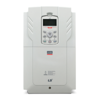
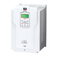
Illustrates and labels the various parts of the inverter for different kW models.
Outlines ideal operating and installation conditions including ambient temperature, humidity, altitude, and vibration.
Provides points to consider when choosing an installation location, including wall support, vibration, and air circulation.
Details specifications for power and signal cables, including ground wire and input/output power wire requirements.
Presents a step-by-step sequence for inverter installation and testing.
Shows a typical system configuration with the inverter and peripheral devices.
Provides procedures for mounting the inverter on a wall or inside a panel, including drilling and bolt tightening.
Instructions to remove the protective insulation strip and enable the RTC feature on the H100 series inverters.
Details on opening the terminal cover, removing cable guides, and connecting cables to power and control terminals.
A table to verify that the inverter has been safely and correctly installed after completion.
Instructions to test the inverter after completing the post-installation checklist, including power on and motor rotation checks.
Describes the keypad layout, display, and operation keys (MODE, PROG/ENT, ESC, HAND, OFF, AUTO, MULTI).
Explains how to navigate between groups, select codes, and set parameter values using the keypad.
Details how to monitor faults that occur during inverter operation and view fault trip histories.
Demonstrates how to revert all parameter settings back to factory defaults.
Describes how to select and switch between the inverter's operation modes (HAND, AUTO, OFF).
Explains various methods to set and modify a frequency reference for operation using keypad, analog inputs, or RS-485.
Describes how to hold operation frequency using a multi-function input as the analog frequency hold terminal.
Explains how to change the units used to display the operational speed of the inverter.
Describes how multi-step operations can be carried out by assigning different speeds or frequencies to Px terminals.
Details how various devices can be selected as command input devices for the inverter.
Explains how to configure prevention to stop motors from running in one direction.
Describes the feature to set up an inverter operation after powering up based on run commands.
Explains how to set up reset and restart operations for inverter operation following a fault trip.
Details how to set acceleration and deceleration times based on maximum frequency or operation frequency.
Explains how to configure gradient level patterns to enhance and smooth acceleration and deceleration curves.
Describes how to configure multi-function input terminals to stop acceleration or deceleration.
Explains how to configure output voltages, gradient levels, and output patterns to achieve target output frequency.
Explains how to adjust output voltage during low speed operation or motor start.
Details how to configure output voltage settings when the motor's rated voltage differs from the input voltage.
Explains how to select the start mode to use when the operation command is input with the motor in the stopped condition.
Explains how to select a stop mode to stop the inverter operation.
Explains how operation frequency can be limited by setting maximum frequency, start frequency, upper limit, and lower limit.
Describes how to apply two types of operation modes and switch between them as required.
Explains how to configure filter time constants and the type of multi-function input terminals.
Explains how to set the availability of using On/Off Delay about Multi-function Input Terminal.
Use main and auxiliary frequencies in predefined formulas to create various operating conditions for fine-tuning operation speeds.
Manual operation where the inverter operates based on parameter settings for jog operation while the Jog command button is pressed.
Uses upper and lower limit value switch output signals as Acc/Dec commands to motors.
Latches the signal input and is used when operating the inverter with a push button.
Allows inverter operation only after a signal is input to the multi-function terminal designated for safety.
Maintains torque during application and release of mechanical brakes on lift-type loads.
Ensures the motor rotates at a constant speed by compensating for motor slip as a load increases.
Provides automated control of flow, pressure, and temperature by adjusting output frequency.
When operation continues below PID conditions for a set time, PID reference is raised to extend standby time.
Automatically measures motor control parameters to optimize the inverter's control mode performance.
Maintains DC link voltage during power interruptions by controlling output frequency to delay low voltage fault trip.
Reduces voltage supplied to motors during low-load and no-load conditions to save energy.
Prevents fault trips when inverter voltage output is disconnected while the motor is idling.
Automatically restarts the inverter when a trip condition is released after stops due to protective devices.
Switches equipment operation by connecting two motors to one inverter, configuring and operating the second motor.
Switches the power source for the motor from inverter output to commercial power source, or vice versa.
Controls the heat-sink cooling fan on and off for situations with frequent load stops/starts or noise-free environment.
Sets standard values and controls output relays or multi-function output terminals based on analog input value.
Prevents braking during regeneration process in press operations by increasing motor operation speed.
Controls the fan motor optimally when a damper is used in the system.
Supplies lubricant to machinery before starting the inverter and the connected mechanical system.
Compensates for pressure loss in a system with long pipelines.
Displays energy savings compared to using a commercial power source without an inverter.
Cleans pumps by removing scales and deposits attached to the impeller through repetitive run-and-stop operations.
Sets initial operating conditions for a pump by adjusting acceleration and deceleration times.
Prevents possible pump damage caused by abrupt deceleration.
Creates load-specific curves for light load operations and pump clean operation.
Detects and displays the level set by the user.
Detects breakages in the pipeline during a PID operation.
Prevents motors and pumps from freezing when they are not operated.
Uses the built-in real-time clock (RTC) to operate the inverter according to the desired time schedule.
Operates the inverter to cope with emergency situations like fire by controlling ventilation fans.
Covers protective functions against overheating damage to the motor.
Details protective functions against inverter malfunctions.
Lists underload fault trip and warning features of the H100 series inverter.
Explains how to set the cooling fan fault mode and output signals for fan faults.
Describes what happens when inverter input power is lost and DC link voltage drops.
Explains how the inverter disconnects output and displays low voltage '2' if DC voltage decreases.
Describes how to block inverter output by setting the multi-function input terminal as the output block signal.
Explains how to restart the inverter using the keypad or analog input terminal to reset the trip status.
Sets the operation mode for communication errors or when an option card is detached during operation.
Detects and protects against faults when the motor is disconnected from the inverter output terminal.
Detects problems like broken belts or couplings while a pump is used.
Examines the life cycle of parts like fans and main capacitors for safer inverter usage.
Lists the types of faults and warnings that can occur with the H100 inverter.
Details RS-485 communication standards, including interface, transmission type, and speed.
Explains how to configure the communication system, including line connection and parameters.
Guides on setting communication parameters such as inverter ID, protocol, and speed.
Describes setting operation command and frequency via communication.
Explains how to configure command loss decision standards and protective operations during communication problems.
Details setting virtual multi-function inputs and saving parameters defined by communication.
Provides a comprehensive map of communication memory areas and their specifications.
Explains how to define parameter groups for data transmission via communication.
Describes defining user/macro parameter groups for communication using USR and MAC addresses.
Explains the slave device (inverter) response to read and write requests from the master device.
Details the function code and protocol for Modbus-RTU communication.
Introduces BACnet as a communication network for building automation and defines standardized objects.
Provides instructions to configure the Metasys-N2 network for a quick start.
Lists parameters for the Drive Group (DRV) that are displayed only when related codes are selected.
Lists parameters for the Basic Function Group (BAS) that are displayed only when related codes are selected.
Lists parameters for the Expanded Function Group (ADV) that are displayed only when related codes are selected.
Lists parameters for the Control Function Group (CON) that are displayed only when related codes are selected.
Lists parameters for the Input Terminal Group (IN) that are displayed only when related codes are selected.
Lists parameters for the Output Terminal Block Function Group (OUT) that are displayed only when related codes are selected.
Lists parameters for the Communication Function Group (COM) that are displayed only when related codes are selected.
Lists parameters for the Advanced Function Group (PID Functions) that are displayed only when related codes are selected.
Lists parameters for the Application 1 Function Group (AP1) that are displayed only when related codes are selected.
Lists parameters for the Application 2 Function Group (AP2) that are displayed only when related codes are selected.
Lists parameters for the Application 3 Function Group (AP3) that are displayed only when related codes are selected.
Lists detailed parameter settings for each macro configuration.
Explains how to troubleshoot problems with inverter protective functions, fault trips, warnings, or faults.
Explains how to replace the cooling fan, perform regular inspections, store, and dispose of the product.
Provides detailed input and output specifications, product details, external dimensions, and peripheral devices.
Details how the inverter displays information for faults, trips, and warnings.
Provides possible causes and remedies for faults not identified as trip trips or warnings.
Covers daily and annual inspection lists for the inverter.
Instructions for replacing the RTC battery, including specifications and safety precautions.
Provides guidelines for storing the product for extended periods and disposing of it as industrial waste.
Details electrical specifications for three-phase input and output, including applied motor, rated output, and rated input.
Provides overall product specifications, including control method, frequency settings, and operation functions.
Illustrates and provides dimensions (W, H, D) for different inverter models.
Lists compatible circuit breakers, leakage breakers, and magnetic contactors manufactured by LS ELECTRIC.
Details specifications for AC input fuses, AC reactors, and DC reactors.
Provides specifications for terminal screw sizes and torque for input/output and control circuits.
Explains dynamic braking units (DBU) and resistors, including terminal arrangements and wiring.
Explains derating by carrier frequency and input voltage, and provides derating graphs and tables.
Form to fill for product warranty, including product name, model, installation date, and customer/retailer details.
Lists cases where a service fee will be incurred for malfunctions, such as abuse, nature acts, or unauthorized modifications.
| Series | LSLV-H100 |
|---|---|
| Type | DC Drives |
| Protection Features | Overcurrent, Overvoltage, Undervoltage, Overheat |
| Communication | RS-485 (Modbus RTU) |
| Cooling Method | Fan Cooled |
| Storage Temperature | -20-60°C |
| Humidity | 5% to 95% RH, non-condensing |
| Dimensions | Varies by model (refer to specific model datasheet) |
| Weight | Varies by model (refer to specific model datasheet) |