4 -14
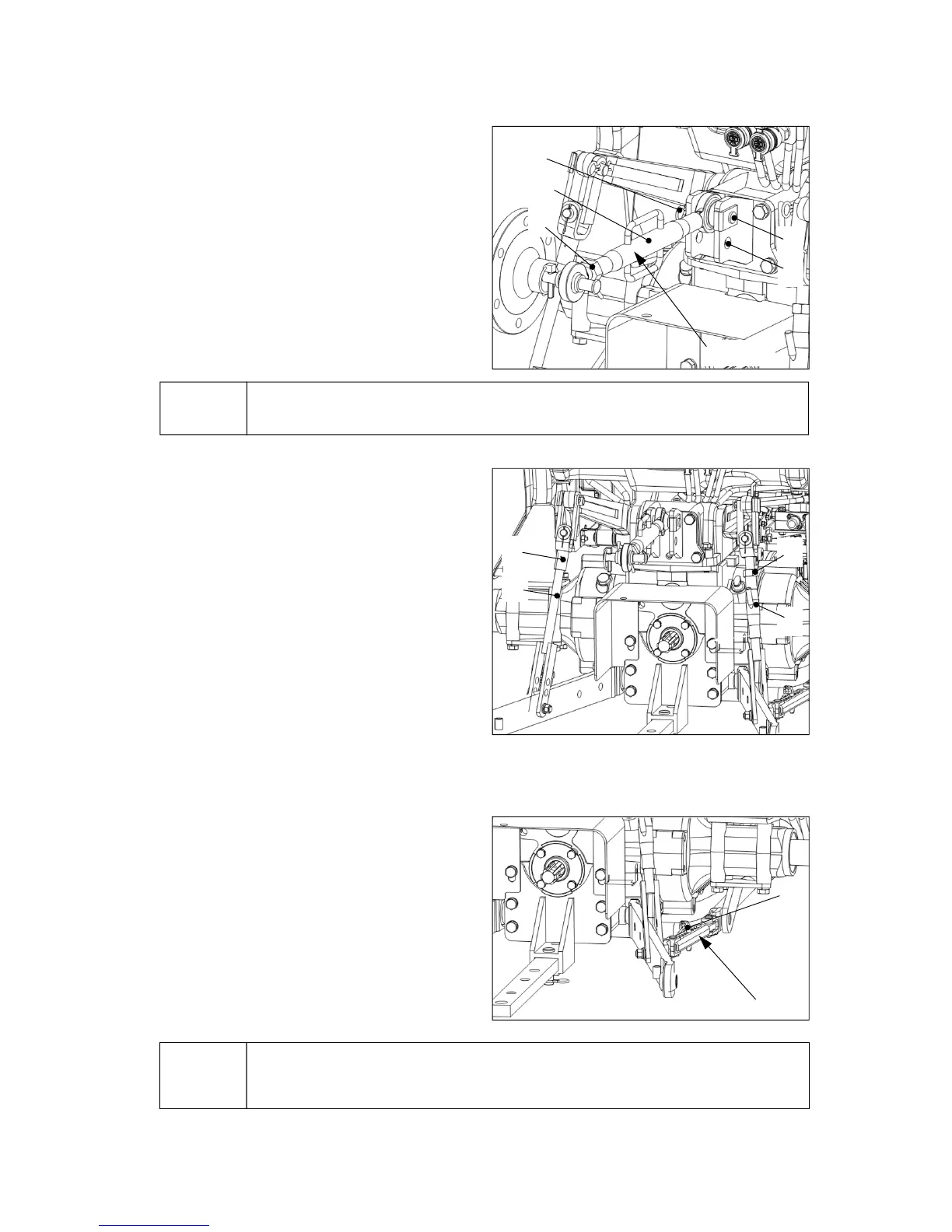
① Upper link installation and
adjustment
z Select the suitable attaching hole(2) depending
on the implement.
z Adjust the length of the upper link by turning the
sleeve(4) after releasing the locking nut (3).
z Fasten the locking nut (3).
z Adjustment range : 400~750mm (15.7~29.5 in)
▶ Insert the snap-pin(6) firmly to prevent the upper link pin(5) from being escaped.
Notice
② Adjustment of lift-rod (Left/Right)
z For lift rod (LH), detach the upper side from the
lift arm and adjust the length by turning the
upper side (1).
-Adjustment range : 492~502mm (19.4~19.8 in)
z For lift rod (RH), turn the handle(4) to the right to
shorten the rod. If turning it to the left, the rod is
elongated. After adjustment, tighten the locking
nut(3).
- Adjustment range : 445~538mm (17.5~21.2 in)
z If assembling the lower link to the upper hole of
the lift rod, it can additionally shorten the length
by 63mm(2.5 in).
⑥
④
②
⑤
③
④
③
①
②
①
Telescopic stabilizer
③ Adjustment of stabilizer (optional)
- Telescopic type
z Pull up the link pin(1) and find a suitable hole
with adjusting the stabilizer’s length.
z Insert the link pin(1) into the hole and let it
tightened firmly by locking spring.
▶When adjusting the stabilizer’s length, adjust the implement’s swinging clearance to
be 20~40mm (0.8~1.6 in.) left and right.
Notice
Upper link