Chapter 6 - Parameter Description [EXT]
141
EXT-34: LM (Load Meter) Output – Sub-A
EXT-35: LM Adjustment
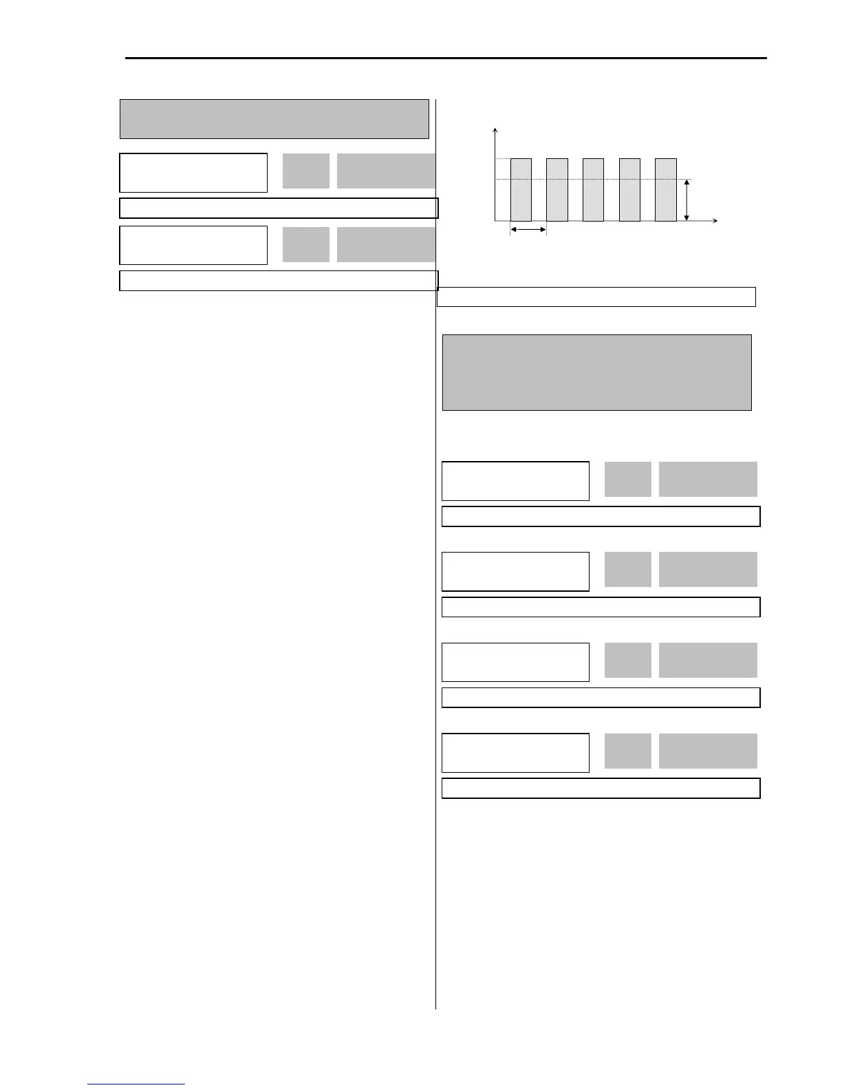
Load meter displays the inverter output Frequency,
Current, Voltage and DC link voltage with pulse signals
on the LM terminal of Sub-A board. The average ranges
from 0V to 10V. EXT-35 is used to adjust the LM value.
[Frequency]
LM terminal outputs inverter output frequency. The
output value is determined by,
LM Output Voltage = (Output freq. / Max. freq.) × 10V ×
FM output gain (I/O-41) / 100
[Current]
LM terminal outputs inverter output current. The output
value is determined by,
LM Output Voltage = (Output current / Rated current) ×
10V × X FM output gain (I/O-41) / 150
[Voltage]
LM terminal output inverter output voltage. The output
value is determined by,
LM Output Voltage = (Output voltage / Max. output
voltage) × 10V × FM output gain (I/O-41) / 100 [DC link
vtg]
LM terminal outputs the DC link voltage of inverter. The
output value is determined by,
LM Output Voltage = (DC link voltage / Max. DC link
voltage) × 10V × FM output gain (I/O-41) / 100
[Torque]
FM terminal outputs the motor torque. The output value
is determined by,
FM terminal output voltage= (Torque current/Rated
torque current) X10V X FM output gain (I/O-41) / 150
[LM Output (LM-CM terminal)]
EXT-40: AM1 (Analog Meter 1) Output – Sub-C
EXT-41: AM1 Adjustment
EXT-42: AM2 (Analog Meter 2) Output – Sub-C
EXT-43: AM2 Adjustment
These terminals are provided on Sub-C board.
Analog meter displays the inverter output Frequency,
Current, Voltage, DC link voltage and Torque with
analog voltage on the AM1 and AM2 terminals of Sub-C
board. The output voltage ranges from 0V to 10V. EXT-
41 and EXT-43 are used to adjust the AM output value.
[Frequency]
The AM terminal outputs inverter output frequency. The
output value is determined by,
AM Output Voltage = (Output freq. / Max. freq.) × 10V X
AM Output Gain (EXT41~42)/ 100
EXT►
LM mode
34 Current
1
 Loading...