Related Manual
Read this data sheet carefully prior to any operation, mounting, installation or start-up of the
product.
GLOFA-GMWIN Programming software
GLOFA-GMWIN Instruction & Programming
GLOFA-GM/MASTER-K Smart I/O User’s manual
GLOFA-GM Pnet I/F Module User’s Manual
KGLWIN(Programming software)
MASTER-K Instruction & Programming
XG5000 Programming software
XGK/XGB Instruction & Programming
XGI/XGR/XEC Instruction & Programming
XGT Pnet I/F Module User’s Manual
Revision History
Head office address and Group CI changed
2011.05 V3.0
KOREAN/ENGLISH data sheet integrated
CI Changed
2013.11 V3.1
Terminal block screwing torque added
Domain of Homepage changed
Terminal block drawing edited.
1. General Specifications
1
Operating
temperature
0 ~ 55℃ -
2
temperature
-25 ~ 70℃ -
3
Operating
5 ~ 95%RH, non-condensing -
4
humidity
5 ~ 95%RH, non-condensing -
5
Vibration
resistance
For discontinuous vibration - -
Frequency
Acceleration
Amplitude times
IEC61131-2
10≤f∠57 Hz - 0.075 mm
10 times in
each
direction
for
X, Y, Z
57 ≤f≤150 Hz 9.8㎨ (1G) -
For continuous vibration
Frequency
Acceleration
Amplitude
10≤f∠57 Hz - 0.035 mm
57≤f≤150 Hz 4.9㎨(0.5G) -
6
Shocks
resistance
•
Max. impact acceleration : 147 ㎨ (15G)
•
Authorized time : 11㎳
•
Pulse wave : Sign half-wave pulse
(Each 3 times in X,Y,Z directions)
IEC61131-2
7
Noise
resistance
impulsenoise
DC: ±900V
standard
Electrostatic
Voltage: 4kV (Contact discharge)
IEC61131-2
IEC61000-4-2
electromagnetic
field noise
80 ~ 1,000 MHz, 10 V/m
IEC61131-2
IEC61000-4-3
Fast transient
/burst noise
Segment
Power
supply
module
input/output
communication
interface
IEC61131-2
IEC61000-4-4
Voltage 2 kV 1 kV
8
Ambient
No corrosive gas or dust -
9
height
2000m or less -
10
Pollution
2 or less -
11
type
Natural air cooling -
2. Performance Specifications
Items
GPL-D22C/D24C/DT4B/C/TR2B/C/TR4B/C/RY2C
Transmission
spec.
Twisted Pair Shielded Cable
Comm. Distance
number
99
Max. Node
number
32
Input : 4Byte / Output : 4Byte
Basic spec
External current
consumption(mA)
GPL-D22C : 70 / GPL-D24C : 85
GPL-DT4B/C : 100 / GPL-TR2B/C : 85
GPL-TR4B/C : 115 / GPL-RY2C : 160
Weight(g)
GPL-D22C : 188 / GPL-D24C : 286
GPL-DT4 B/C : 254/284 /GPL-TR2 B/C : 160/189
GPL-TR4 B/C : 255/285 / GPL-RY2C : 332
3. Cable Specifications
(1) Belden Network Cable
(a) Type : Network Components
(b) Protocol : FMS-DP-PA
(c) Certification : No
(d) Order No. : 3077F, 3079A
Method
PE-Polyethylen
0.035 (Inch)
Shield
Polyester Tape/Braid
㎊
150Ω
(2) Connector
4. Wiring of communication cable
(1) Wiring and Termination
(a) Please connect a GREEN line to A1,A2 and a RED line to B1,B2 in general.
In addition, Shield is connected to the clamp of connector.
(b) Please use cable of over 80% shield density.
(c) Please ensure that you have terminated both ends of each segment.
(d) If there are more than 0ne segment, it is necessary that you should
terminate every segment.
5. Parts Name and Descriptions
(1) GPL-D22C/TR2B/TR2C
(2) GPL-D24C/DT4B/DT4C/TR4B/TR4C/RY2C
Connector
Connector for connecting with
communication module
9-PIN Plug 9-pin female connector for Pnet
Part name display section
Display the Part name of Smart I/O
DC Input 16//TR Output 16
Communication LED
Display the status of communication
module
Display the status of power
RDY
Displays the communication status of
Comm. Module
ERR
Displays the abnormal err of comm..
module
×10 Set 10 digit of station number
×1 Set 1 digit of station number
Display the ON/OFF status of module
Display the ON/OFF status of module
Hook for mounting on DIN Rail
Terminal block
screw
In/Output terminal & Power input
GPL-D22C
/
GPL-D24C
Common(16 points/COM)( GPL-D22C)
Common(16 points/COM)( GPL-D24C)
GPL-DT4B
/
GPL-DT4C
GPL-TR2B/C
/
GPL-TR4B/C
Output terminal(GPL-TR2B/TR2C)
Output terminal(GPL-TR4B/TR4C)
Common(16 points/COM) (GPL-TR2B/C)
Common(16 points/COM) (GPL-TR4B/C)
GPL-RY2C
6. Specification of Input/Output Module
(1) GPL-D22C/D24C/DT4B/DT4C(Input)
Number of input points 16 points 32 points 16 points
Rated Input
Current
B 7 mA
C/C1 5 mA
Operating Voltage Range DC 20.4~28.8V(ripple: less than 5%)
ON Voltage DC 19V or less
OFF Voltage DC 6V or less
Response
Time
OFF
→
ON 0~3ms or less
ON
→
OFF 0~3ms or less
Common Terminal 16 points/COM
Operating indicator LED turns on at ON state of input
External connections Terminal block connector(M3
×
6 screws)
Insulation Method Photo Coupler
(a) External Connection
<GPL-D22C> <GPL-D24C> <GPL-DT4B/C>
15
13
11
09
07
05
03
01
DC
24G
DC
24V
14
10
08
06
04
02
00
COM1
FG
12
+
+
-
-
13
11
09
07
05
03
01
DC
24G
DC
24V
10
08
06
04
02
00
COM
FG
12
15
COM
14
+
-
+
-
+
-
+
-
30
18
16
15
03
01
DC
24G
DC
24V
31
17
04
02
00
FG
19
+
+
-
-
COM1
COM0
+
-
+
-
+
-
(2) GPL-TR2B/TR4B/DT4B/TR2C/TR4C/DT4C(Output)
Number of output points 16 points 32 points 16 points
Rated load voltage DC 24V
Max. load current 0.5A/point, 3A/COM
OFF leakage current 0.1mA or less
Max. inrush current 4A /10ms or less
Maximum voltage drop
DC 1.0V or less
External
DC 24V
±
10%(ripple voltage : 4Vp-p or less)
Response
LED turns on at ON state of output
Terminal block connector (M3
×
6 screws)
(a) External Connection
<GPL-TR2B/C> <GPL-TR4B/C> <GPL-DT4B/C>
15
COM1
0V
13
11
09
07
05
03
01
DC
24G
DC
24V
10
08
06
04
02
00
FG
12
L 15
COM0
14
L
L
L
L
L
L
L
L
L
L
L
L
L
L
L
+
-
+
-
30
18
16
15
03
01
DC
24G
DC
24V
0V
31
17
04
02
00
FG
19
COM1
COM0
+
-
+
-
L
L
L
L
L
L
L
L
L
L
L
L
+
-
13
11
09
07
05
03
01
DC
24G
DC
24V
0V
10
08
06
04
02
00
COM
FG
12
L 15
COM
14
L
L
L
L
L
L
L
L
L
L
L
L
L
L
L
+
-
+
-
(3) GPL-RY2C
Number of output points 16 points
Rated load voltage/current DC24V/AC220V, 2A(Cos
ϕ
=1)/point 5A/COM
Minimum load voltage/current DC 5V/1mA
Minimum load voltage/
Maximum switching frequency
AC 250V DC 110V, 1,200 times/hour
Time
Service
Life
Electrical
Rated load voltage/current 100,000 times or more
AC 200V/1.5A,AC 240V/1A(Cos
ϕ
=0.7) 100,000 times
or more
AC 200V/1A,AC 240V/0.5A(Cos
ϕ
times
or more
DC 24V/1A,DC 100V/0.1A(L/R=7ms) 100,000 times
or more
LED turns on at ON state of output
Terminal block connector(M3
×
6 screws)
(a) External Connection
DC
24V
DC
24G
01 02 05 06 09 10 13 14
COMA COMA C OMA COMC COMC COMC
FG
03 04 07 08 11 12 15
COMB COMC COM C COMDCOMA
00
COMA
L LL L L L L L
L L L L
L L L L
+ -
* Internally, The COMA and COMC are wired each other.
7. Precaution on installation
(1) When setting up the network, be sure not to duplicate the station number.
If there is any duplicated station number, the communication will not be established.
(2) Use cable complied with specification of this data sheet. Otherwise, it can cause serious
communication error.
(3) Make sure that communication cable connector fastened firmly. Otherwise, it can cause
serious communication error.
(4) Improper cable connection (snarled cable, redundant connection, etc) can cause
communication error.
(5) Do not place communication cable near power cable or inductive noise source.
(6) Change of station number will not take effect before power is re-applied.
8. Dimension (
)
(1) GPL-D22C/TR2B/TR2C
(2) GPL-D24C/TR4B/TR4C/DT4B/DT4C/RY2C
9. Warranty
(1) Warranty period
LSIS provides an 18-month-warranty from the date of the production.
(2) Warranty conditions
For troubles within the warranty period, LSIS will replace the entire PLC or
repair the troubled parts free of charge except the following cases.
(a) The troubles caused by improper condition, environment or treatment
except the instructions of LSIS.
(b) The troubles caused by external devices.
(c) The troubles caused by remodeling or repairing based on the user’s own
discretion.
(d) The troubles caused by improper usage of the product.
(e) The troubles caused by the reason which exceeded the expectation from
science and technology level when LSIS manufactured the product.
(f) The troubles caused by natural disaster.
(3) This warranty is limited to the PLC itself only. It is not valid for the whole system
which the PLC is attached to.
• HEAD OFFICE
LS Tower, 127, LS-ro, Dongan-gu, Anyang-si,Gyeonggi-do, 431-848, Korea
Tel : 82-2-2034-4870 Fax: (82-2)2034-4648 e-mail: cshwang@lsis.com
• LSIS(ME) FZE _ Dubai, U.A.E.
Tel: 971-4-886-5360 Fax: 971-4-886-5361 e-mail: jungyongl@lsis.com
• LSIS Tokyo Office _ Tokyo, Japan
Tel: 81-3-3582-9128 Fax: 81-3-3582-2667 e-mail: jschuna@lsis.com
• LSIS Shanghai Office _ Shanghai, China
Tel: 86-21-5237-9977(609) Fax: 89-21-5237-7189 e-mail: liyong@lsis.com.cn
• LSIS Beijing Office _ Beijing, China
Tel: 86-10-5825-6027(666) Fax: 86-10-5825-6028 e-mail: xunmj@lsis.com.cn
• LSIS Guangzhou Office _ Guangzhou, China
Tel: 86-20-8328-6754 Fax: 86-20-8326-6287 e-mail: chenxs@lsis.com.cn
• LSIS Chengdu Office _ Chengdu, China
Tel: 86-20-8328-6754 Fax: 86-20-8326-6287 e-mail: comysb@lsis.com
• LSIS Qingdao Office _ Qingdao, China
Tel: 86-532-8501-6068 Fax: 86-532-8501-6057 e-mail: wangzy@lsis.com.cn
• LSIS Europe B.V., Netherlands
Tel: +31 (0)20 654 1420 Fax: +31(0)20 654 1429 e-mail: junshickp@lsis.com
• Homepage: http://www.lsis.com
LS constantly endeavors to improve our products so that information in this
datasheet is subject to change without notice
.
The date of issue: 2013. 11
10310000448 Ver 3.2
GPL-TR4B
GPL-DT4B
GPL-D22C
GPL-D24C
GPL-DT4C
GPL-TR2C
GPL-TR4C
LS Programmable Logic Controller
Pnet(Profibus-DP) I/F Module
- When using LSIS equipment, thoroughly read this
datasheet and associated manuals introduced in this
datasheet. Also pay careful attention to safety and handle
the module properly.
- Store this datasheet in a safe place so that you can take it
out and read it whenever necessary.
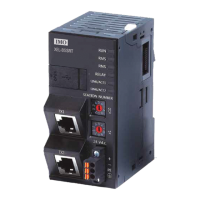
Smart I/O
Caution
► Be sure to check the rated voltage and terminal arrangement for the
module before wiring work.
Risk of electric shock, fire and malfunction.
► Tighten the screw of terminal block with the specified torque range.
If the terminal screw is loose, it can cause fire and electric shock.
► Use the PLC in an environment that meets the general
specifications contained in this datasheet.
Risk of electrical shock, fire, erroneous operation and deterioration of the
PLC.
► Be sure that external load does not exceed the rating of output
module.
Risk of fire and erroneous operation.
► Do not use the PLC in the environment of direct vibration
Risk of electrical shock, fire and erroneous operation.
► Do not disassemble, repair or modify the PLC.
Risk of electrical shock, fire and erroneous operation
► When disposing of PLC and battery, treat it as industrial waste.
Risk of poisonous pollution or explosion.
► Do not Install other places except PLC controlled place.
►
Make sure that the FG terminal is grounded with class 3 grounding which is
dedicated to the PLC. Otherwise, it can cause disorder or malfunction of PLC
► Connect expansion connector correctly when expansion module is needed.
► Do not detach PCB from the case of the module and do not modify the module.
► Turn off power when attaching or detaching module.
► Cellular phone or walkie-talkie should be farther than 30cm from the PLC.
► Input signal and communication line should be farther than 10cm from a high-
tension and a power line in order not to be affected by noise and magnetic field.
Others PLC Others PLC PLC Others
Safety Precautions
► Safety Precautions is for using the product safely and correctly
the accidents and danger, so please go by them.
► The precautions explained here only apply to this module. For
on the PLC system, refer to User’s manual.
►
The precautions are divided into 2 sections, ‘Warning’ and ‘Caution’. Each of the
meanings is represented as follows.
If you
violate instructions, it can cause death, fatal injury or a
considerable loss of property
If you violate instructions, it can cause a slight injury or a slight
loss of products
► The symbols which are indicated in the PLC and User’s Manual mean as follows.
This symbol means paying attention because of danger of injury, fire,
or malfunction
► This symbol means paying attention because of danger of electric shock.
Store this datasheet in a safe place so that you can take it out and read
it whenever necessary. Always forward it to the end user
Handing Precautions
► Don’t drop or make impact.
► Don’t detach PCB from case. It may cause problem.
► When wiring, let no foreign material go into the module. If it goes into the module,
remove it.
► Don’t detach the module from slot while power is on
Warning
► Do not contact the terminals while the power is applied.
Risk of electric shock and malfunction.
► Protect the product from being gone into by foreign metallic matter.
Risk of fire, electric shock and malfunction.
► Risk of fire, electric shock and malfunction.
Risk of injury and fire by explosion and ignition.