T
Thomas HunterAug 6, 2025
What does 'Over Current 2' mean on my LS Controller?
- RRobert WilliamsAug 6, 2025
The LS Controller turns off the output if an IGBT short through or an output short occurs.
What does 'Over Current 2' mean on my LS Controller?
The LS Controller turns off the output if an IGBT short through or an output short occurs.
What does 'MC Fail' mean on my LS Controller?
The message 'MC Fail' is displayed when input power is not applied or when the M/C inside the LS Controller malfunctions.
Defines the highest level of hazard, indicating immediate risk of death or serious injury.
Alerts to potential for death or serious injury if instructions are not followed.
Warns of potential minor injury or property damage due to non-compliance.
Diagram and explanation of fundamental wiring connections for power and control circuits.
Details on different power terminal configurations for various inverter models.
Description of various control terminals and their functions for input and output signals.
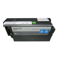
A step-by-step walkthrough for operating the inverter via the keypad.
Detailed description of FU1 group parameters.
Detailed description of FU2 group parameters.
Detailed description of I/O group parameters.
Information on DB resistor options.
Description and models of the DB Unit.
| Model | SV037iS5-4 |
|---|---|
| Category | Controller |
| Power | 3.7 kW |
| Number of Axes | 1 |
| Communication Interface | RS-485 |
| Protection Class | IP20 |
| Input Voltage | 380-480 VAC |