C
Colin PetersAug 6, 2025
What does 'Over Current 2' mean on my LS Controller?
- KKenneth TurnerAug 6, 2025
The LS Controller turns off the output if an IGBT short through or an output short occurs.
What does 'Over Current 2' mean on my LS Controller?
The LS Controller turns off the output if an IGBT short through or an output short occurs.
What does 'MC Fail' mean on my LS Controller?
The message 'MC Fail' is displayed when input power is not applied or when the M/C inside the LS Controller malfunctions.
Lists the seven parameter groups (DRV, FU1, FU2, I/O, EXT, COM, APP) and their descriptions.
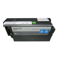
Illustrates the LCD keypad layout and describes the function of each button for navigation and data entry.
Explains the 7-segment keypad layout, encoder knob, and button functions for parameter navigation and data entry.
Details the available operation methods: using keypad, control terminals, both, or option board.
Covers basic and advanced function parameter settings, including common parameters and V/f control settings.
Provides detailed operational examples for various control modes, including V/F, Sensorless S, and Vector SPD.
Step-by-step guide for operating the inverter using the keypad, covering power application and basic control.
Instructions for operating the inverter using external control terminals like potentiometer and signal inputs.
Details two methods: frequency set by external source and run/stop by keypad, or vice versa.
Lists inverter faults, their protective functions, and descriptions, including keypad and 7-segment displays.
Provides a table matching protective functions with potential causes and recommended remedies for faults.
Offers a checklist of conditions and corresponding check points to diagnose and resolve common inverter issues.
Guides on checking power components like diode modules, resistors, and IGBTs using a tester.
Covers essential precautions, routine inspections, periodical inspections, and internal fuse replacement.
A comprehensive checklist for daily and periodic inspections covering various aspects of the inverter and motor.
| Braking Unit | Built-in |
|---|---|
| Protection Level | IP20 |
| Control Method | V/F control, Sensorless vector control |
| Power (kW) | 2.2kW |
| Power (HP) | 3HP |
| Input Voltage | 3-phase 380-480V |
| Input Frequency | 50/60Hz |
| Protection Functions | Overcurrent, Overvoltage, Undervoltage, Overheat, Short circuit |
| Storage Temperature | -20~65°C |