EasyManuals Logo

LS SV150iS5-4 User Manual

Default Icon
205 pages
To Next Page IconTo Next Page
To Previous Page IconTo Previous Page
Page #177 background imageLoading...
Page #177 background image
Chapter 7 - Options
171
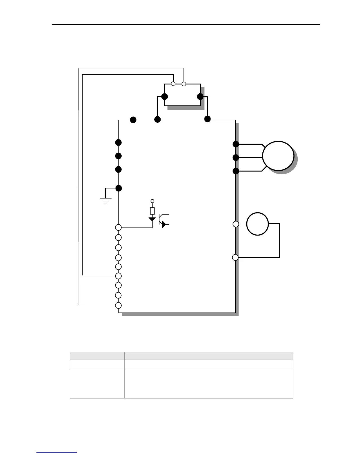
· DB resistor wiring for 15~30HP Built-in DB Unit Inverter
DB resistor terminal Terminal description
B1, B2 Connect the DB Resistor to Inverter terminal B1, B2.
TH1, TH2
Thermal sensors provided with the DB resistor.
P1 is ON (TH1-TH2 Shorted) at normal (ambient temp) and P1 is OFF (TH1-TH2
Open) at overheated status. Connect the thermal sensor to one of the multi-function
input (P1, P2 or P3, I/O 12-14 setting: Ext Trip-B).
IM
U
V
W
G
R
S
T
B1
B2
DB
Resistor
FX
RX
BX
RST
JO
G
P2
P3
FM
+
FM
5G
Analog freq
output
2)
(0-10V)
P1
REV Run / Stop
FWD Run / Stop
Fault reset
Jog
Max Current thru
PC: 5mA
CM
24 V
TH1
TH2
Max distance between inverter and
DB Resistor: 5m
Multi-function input terminal
(I/O-12 Setting: Ext Trip-B)
P1
B2
B1

Questions and Answers:

Question and Answer IconNeed help?

Do you have a question about the LS SV150iS5-4 and is the answer not in the manual?

LS SV150iS5-4 Specifications

General IconGeneral
BrandLS
ModelSV150iS5-4
CategoryController
LanguageEnglish

Related product manuals