Thermo-hygrometer with current outputs – User manual
INSTUM_01378 Pag. 5/12
2.3 Mechanical mounting
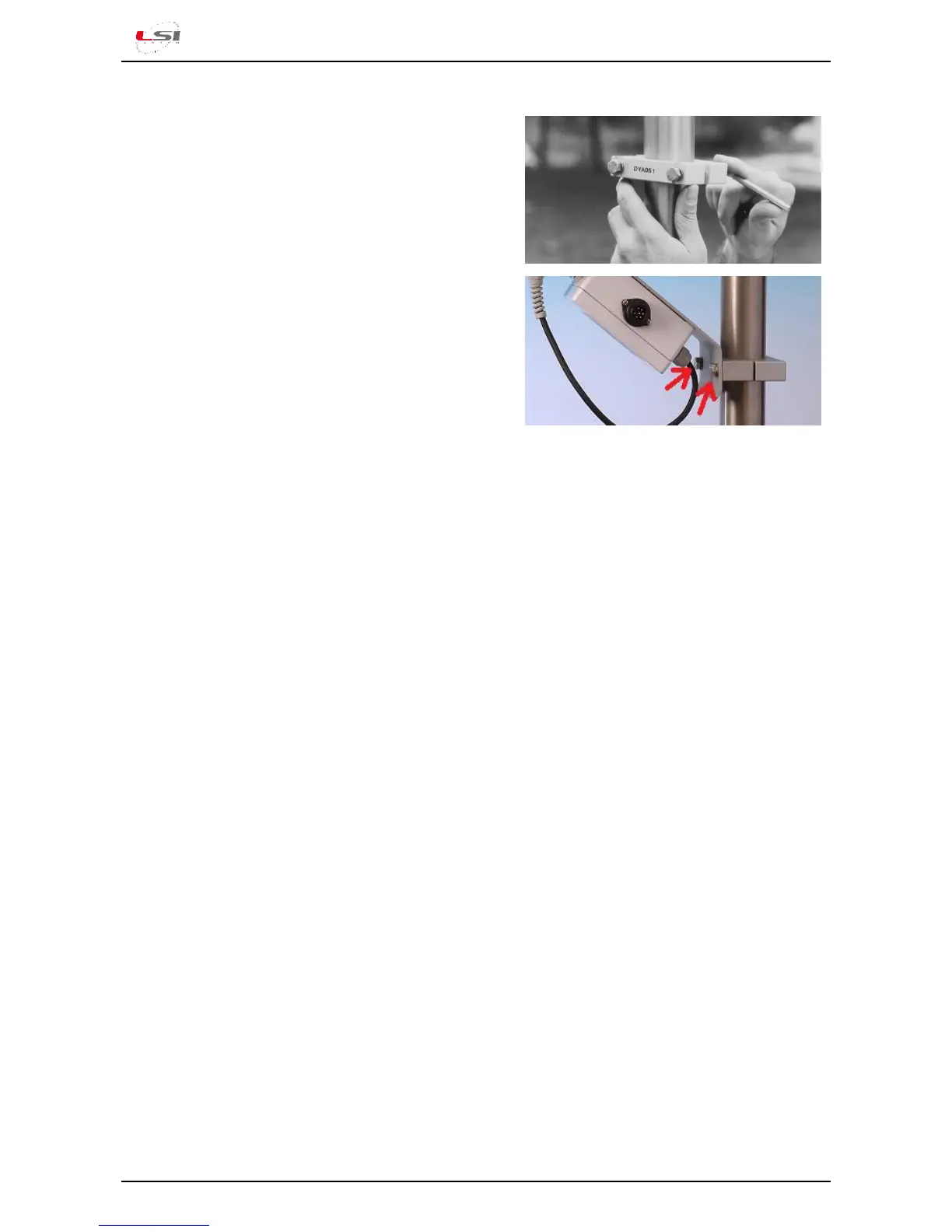
Fit the DYA049 or DYA051 supporting collar to the
pole at the desired height, usually at 1,5 - 2 m, and
tighten the screws using an allen key n. 6.
Fix the sensor to the supporting collar by tightening
the two bolts indicated with arrows in the picture.
Connect the DWA cable to the sensor and to the data
acquisition system according to drawing
DISACC5901d.
when a forced ventilation radiation shield is in use,
feed the fan engine with a suitable power supply.
2.4 Dip-switches configuration
The factory settings are:
Electric output: 4÷20 mA
Hygrometric output: UR %
Temperature range: -30÷70 °C
To change the settings open the sensor box , set the dip-switches according to your needs (the
arrangement of the dip-switches is shown inside the box cover and on the drawing DISACC5901d)
and close the box.
2.5 Electrical connection
Power the instrument according to the technical specifications. For optimal operation, ensure proper
earthling of the power and communication lines.
 Loading...