06
| LSIS Co., Ltd.
Installation Quick Guide
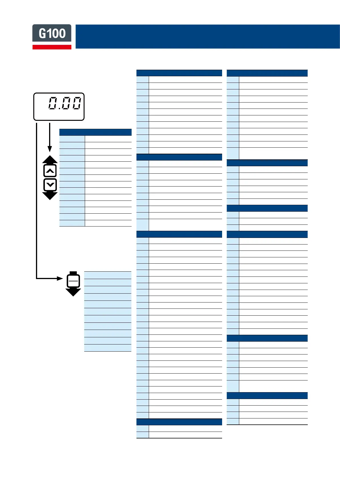
Operation
0.00
Target frequency
ACC
Acceleration time
dEC
Deceleration time
drv
Command source
Frq
Frequency ref. src.
St1
Multi-step freq.1
St2
Multi-step freq.1
St3
Multi-step freq.1
CUr
Output current
Rpm
Motor RPM
dCL
Inverter DC volt.
vOL
Inverter Vout
nOn
Current fault
drC
Rotation select
Drive
09
Control mode
11
Jog frequency
15
Torque boost
19
Start frequency
20
Maximum frequency
26
Auto torque boost filter gain
27
Auto torque boost motoring gain
28
Auto torque boost regeneration gain
81
Select monitor code
93
Parameter initialization
95
Parameter lock settings
97
Software version
Basic
04
2
nd
command source
05
2
nd
frequency source
07
V/f pattern
08
Acc/Dec reference
09
Time scale setting
11
No. of poles
12
Rated slip speed
14
Motor noload current
15
Motor rated voltage
53~
56
Multi-step freq. 4~7
Advanced
01
Acceleration pattern
02
Deceleration pattern
03
S-curve acceleration start point gradient
04
S-curve acceleration end point gradient
05
S-curve deceleration start point gradient
06
S-curve deceleration end point gradient
08
Stop mode
09
Run prevention options
10
Starting with power on
12
Start DC braking time
13
Amount of applied DC
14
Output blocking time before DC braking
15
DC braking time
16
DC braking rate
17
DC braking frequency
24
Frequency limit
25
Frequency lower limit value
26
Frequency upper limit value
41
Brake release current
42
Brake release delay time
44
Brake release forward frequency
45
Brake release reverse frequency
46
Brake engage delay time
47
Brake engage frequency
51
Energy saving amount
63
Rotation count speed unit
64
Cooling fan control
79
DB unit turn on voltage level
Control
04
Carrier frequency
71
Speed search operation selection
Input
01
Frequency for maximum analog input
07
Time constant of V1 input filter
08
V1 minimum input voltage
09
V1 output at minimum input voltage(%)
10
V1 maximum input voltage
11
V1 output at maximum input voltage(%)
52
I2 input filter time constant
53
I2 minimum input current
54
I2 output at minimum input current (%)
55
I2 maximum input current
56
I2 output at maximum input current(%)
65~
69
P1~5 terminal function setting
Output
01 Analog output1 item
02
Analog output1 gain
31~32
Multi-function relay1~2 item
41 Multi-function output monitor
57 FDT detection frequency
58 FDT detection frequency band
Communication
01
Built-in communication inverter ID
02
Built-in communication protocol
03
Built-in communication speed
Application
01
Application function selection
16
PID output monitor
18
PID feedback monitor
19
PID reference setting
20
PID reference source
21
PID feedback source
22
ID controller proportional gain(P-gain)
23
PID controller integral time(I-time)
28
PID mode (process/normal)
29
PID upper limit frequency
30
PID lower limit frequency
37
PID sleep mode delay time
38
PID sleep mode frequency
39
PID wake-up level
42
PID controller unit selection
Protection
12
Motion at speed command loss
20
Motion at overload fault
21
Overload fault level
22
Overload fault time
50
Stall prevention motion and flux braking
79
Cooling fan fault selection
91~
95
Fault history1~5
2
nd
Motor
4
M2 Acceleration time
5
M2 Deceleration time
7
M2 Base frequency
12
M2 Rated current
Drive
Basic
Advanced
Control
Input
Output
Communication
Application
Protection
2
nd
Motor
Configuration
※
Operation group
• Operation group consist of
14 basic parameters
Basic Parameter List
Operation

 Loading...
