02
| LSIS Co., Ltd.
Installation Quick Guide
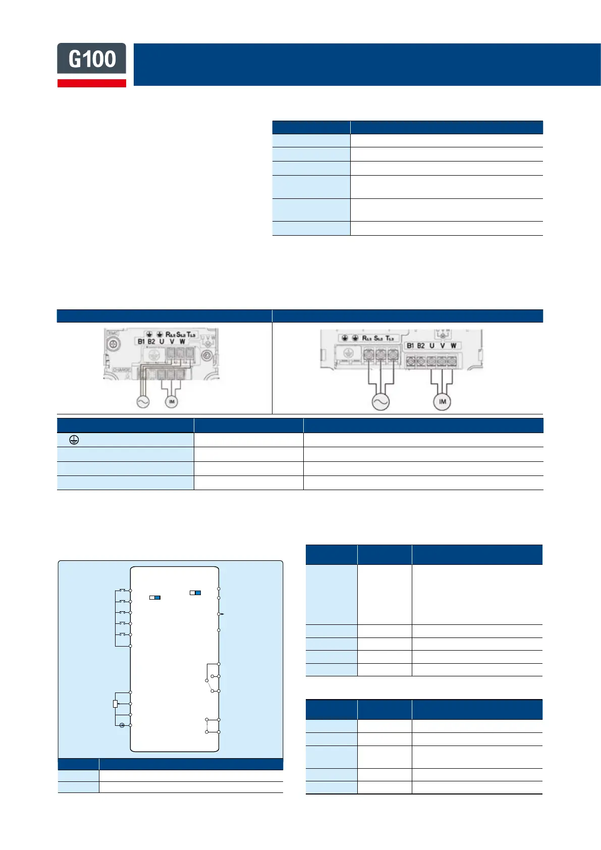
0.4 ~ 4.0kW 5.5 ~ 7.5kW
Power Terminal Wiring
• The following illustration shows the terminal layout on the power terminal block. Refer to the detailed
descriptions to understand the function and location of each terminal before making wiring connections.
• Inverters are composed of various precision,
electronic devices, and therefore the installation
environment can significantly impact the lifespan
and reliability of the product. The table below
details the ideal operation and installation
conditions for the inverter.
* The ambient temperature is the temperature measured at a point 2” (5 cm) from the surface of
the inverter.
Control Terminal Wiring
• The illustrations below show the detailed layout of
control wiring terminals, and control board switches.
• Input terminal labels and descriptions
• Output / Communication terminal labels and descriptions
Labels
Linked
Parameters
Description / Factory Default
P1~P5
IN-65
IN-66
IN-67
IN-68
IN-69
Functions for digital input terminals
P1: FX
P2: Rx
P3: BX
P4: RST
P5: Speed-L
VR
-
Power source for analog freq. source (12V
out
)
V1
IN-05~16
Voltage source for analog input
I1
IN-50~62
Current source for analog input
CM
-
Common terminal
Labels
Linked
Parameters
Description / Factory Default
A1/B1/C1
OU-31 Relay output 1, Default: Trip
A2/C2
OU-33 Relay output 2, Default: Run
AO
-
Analog voltage output terminal
Default: Output Frequency
24
- External 24V power source
S+/S-
- RS-485 signal line
Items Description
Ambient Temperature*
Heavy load: -10–50°C, Normal load: -10–40°C
Ambient Humidity
Less than 95% relative humidity (no condensation)
Storage Temperature
-20 - 65°C
Environmental
Factors
An environment free from corrosive or flammable
gases, oil residue, or dust
Operation Altitude/
Oscillation
Lower than 3,280 ft (1,000 m) above sea level,
less than 1G (9.8 m/sec
2
)
Air Pressure
70–106 kPa
Terminal Labels
Name Description
(SPVOEUFSNJOBM $POOFDUFBSUIHSPVOEJOH
3-4-5- "$QPXFSJOQVUUFSNJOBM .BJOTTVQQMZ"$QPXFSDPOOFDUJPOT
## #SBLFSFTJTUPSUFSNJOBMT #SBLFSFTJTUPSXJSJOHDPOOFDUJPO
678
.PUPSPVUQVUUFSNJOBMT QIBTFJOEVDUJPONPUPSXJSJOHDPOOFDUJPOT
Switch Description
48
/1/1/1NPEFTFMFDUJPOTXJUDI
48
5FSNJOBUJOHSFTJTUPSTFMFDUJPOTXJUDI
34
"OBMPHPVUQVU
%FGBVMU'SFRVFODZ
48
48
/1/ 1/1
0/ 0''
1
1
4
4
"0
1
1
1
1
$.
71PXFS
.VMUJGVODUJPOJOQVU
%FGBVMU
"OBMPHJOQVU
'9
39
#9
345
4QE-
73
7
$.
*
3FMBZPVUQVU
%FGBVMU5SJQ
3FMBZPVUQVU
%FGBVMU3VO
"
$
#
"
$