Power Up: DLP-513 363-205-401
Page 4 of 8 Issue 7, March 1997
13. In battery section of cabinet at power panel, refer to Table A and connect
DMM test leads to
+BAT TEST
jack
J1
or
J3
and −
BAT TEST
jack
J2
or
J4
of
battery string 2.
14. Does meter indicate greater than 45.0 volts DC?
If
YES,
then proceed to Step
18.
If
NO,
then continue with Step
15.
15. Have all battery packs on shelf been replaced?
If
YES,
then proceed to Step
17.
If
NO,
then continue with Step
16.
16. Select another battery pack on battery shelf and repeat from Step
12.
17. Check wiring and connectors on battery shelf. Repeat the procedure from Step
13
after locating and correcting trouble.
18. Remove DMM test leads and reinstall fuses in power panel that were removed
previously.
19. Is battery string 3 to be installed?
If
YES,
then continue with Step
20.
If
NO,
then proceed to Step
40.
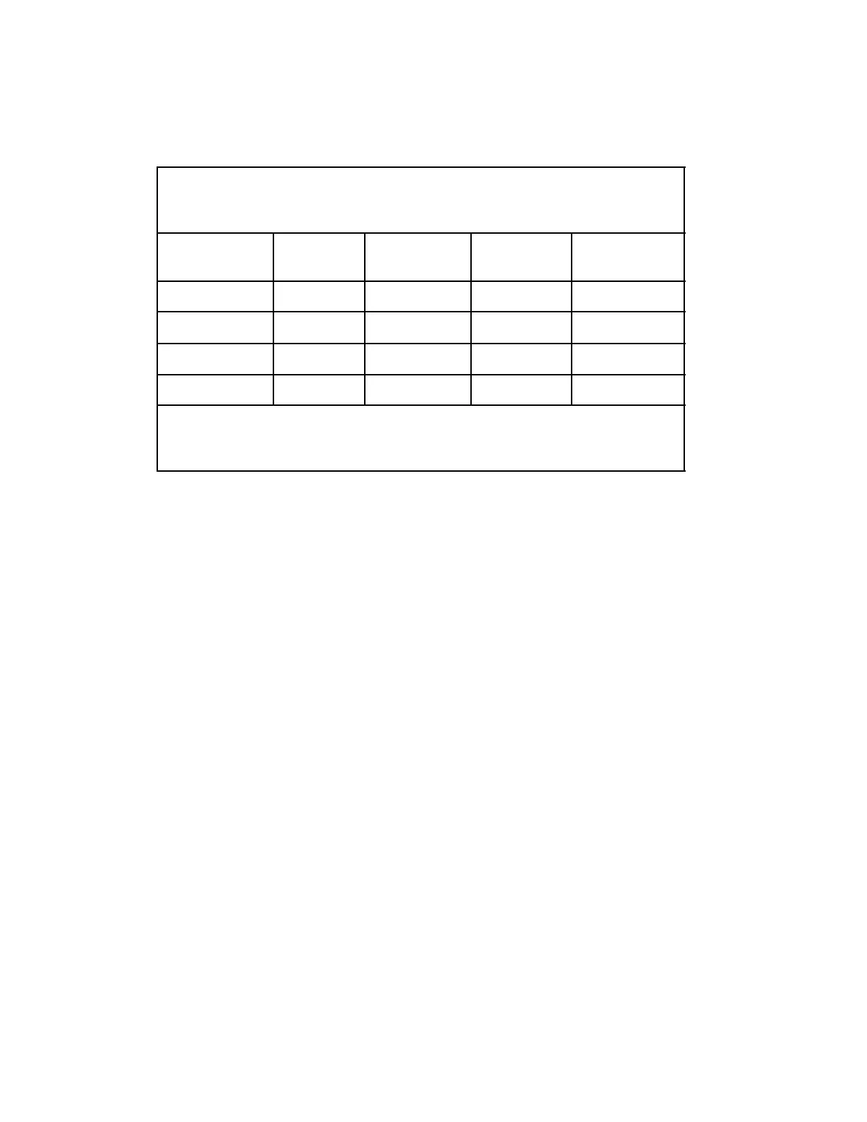
Table A
51A Power Panel
Power Panel
(Note)
Battery
String
Associated
Fuses
Associated
Jacks
Connector
Plug
Early Version 1 (Lower) F3, F4, F5 J3, J4 P5, P6, P7, P8
2 (Upper) F1, F2, F6 J1, J2 P1, P2, P3, P4
Later Version 1 (Lower) F1, F2, F5 J1, J2 P1, P2, P3, P4
2 (Upper) F3, F4, F6 J3, J4 P5, P6, P7, P8
Note:
If the words
51 CABINET POWER PANEL
appear at the top of the power
panel, then the power panel is a later version. Otherwise, the power panel is an
early version.
 Loading...