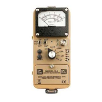
Model 12-4 Technical Manual Section 8
Ludlum Measurements, Inc. Page 8-2 May 2016
Scale Ranging
Detector pulses from the discriminator are coupled to univibrator pin 5 of
U9A. For each scale, the pulse width of pin 6 of U9A is increased by a factor
of 10 with the actual pulse width being controlled by the front-panel
calibration controls and their related capacitors. This arrangement allows the
same current to be delivered to C9 by one count on the ×1 range as 1000
counts on ×1K range.
Digital Analog Converter
U5 is coupled as a current mirror. For each pulse of current through R24
and equal current is delivered to C9. This charge is drained off by R25. The
voltage across C9 is proportional to the incoming count rate.
RateMeter Drive Circuit
Voltage across C9 is measured by voltage follower U10 and Q2. Q2
converts voltage input to a constant current output at Q2 collector. Current
flow is controlled by R19. For slow time constant, C17 is switched from the
output to parallel C9 at the input. Reset (SW2) shorts the input capacitor.
R44 stabilizes U10. Meter current flows through analog switch U7A and
U16B.
HV Meter Drive
A V proportional to HV is converted to a constant current drain by voltage
follower U13 and Q3. Current flow is controlled by R49. This current is
converted to a constant current source by U15, and then coupled to the
meter through analog switches U3B.
Battery Test
Battery voltage is connected through R8 through analog switch U3A and
U16B to the meter.

 Loading...