M310-HT Manual Communications Port • 15
5 Communications Port
5.1 RS232C
This blackbody may have the option to communicate with the temperature controller via a PC or
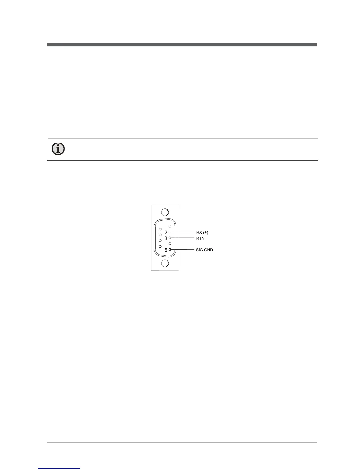
similar device. The DB-9 male connector is on the rear panel. Wiring is shown below. It is wired
to operate with a standard through cable (not null modem). This method allows bi-directional
data transfer via a three conductor cable consisting of signal ground, receive input and transmit
output. It is recommended for communication distances less than fifty feet between the
computer terminal and the instrument.
Note: Multiple instruments cannot be connected to the same port.
The RS232 port is optically isolated to eliminate ground loop problems. Typically, “DATA OUT”
of the computer/terminal connects to the “RCV” terminal on the instrument. “DATA IN”
connects to the “XMT” terminal. If shielded cable is used, it should be connected to the frame
ground at one end only. Signal ground is to be connected at appropriate ground terminals. The
blackbody frame ground is the shield connection for the communication port.
RS232 Wiring
 Loading...