NOTE: See the IDEAS
®
User Manual for more information on features and graphing. The tools functionality is the
same in INSPIRE
™
as in IDEAS.
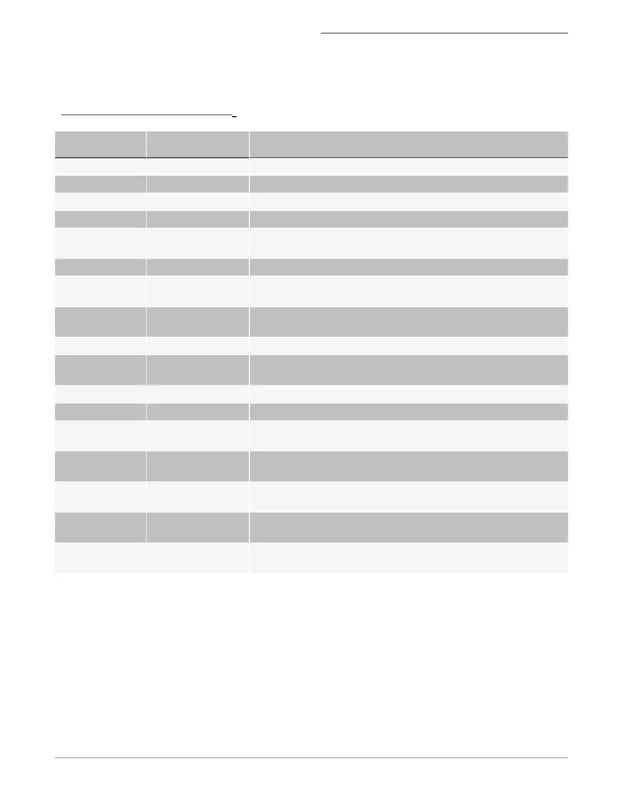
Table 1. Features available for FlowSight
®
Name Mask_Channel Definition
Area M01-M012,MC The size of the mask in square microns.
Aspect Ratio M01-M012 The ratio of the Minor Axis divided by the Major Axis.
Bkgd Mean Ch01-Ch12 The average intensity of the camera background.
Bkgd StdDev Ch01-Ch12 The standard deviation of the background intensities.
Camera Line Num-
ber
none An incremental count of objects.
Camera Timer none The clock rate in KHz. This is relative time.
Gradient RMS
M01_Ch01 through
M12_Ch12
Enumerates changes of pixel values in the image to measure the focus
quality of an image.
Intensity
MC_Ch01 through
MC_Ch12
The sum of the pixel intensities in the mask, background subtracted.
Major Axis M01-M012 Describes the widest part of the mask.
Mean Pixel
M01_Ch01 through
M12_Ch12
The average pixel value within the mask, background subtracted.
Minor Axis M01-M012 Describes the narrowest part of the mask.
Object Number none The sequence of objects.
Raw Centroid X none
The central tendency of the pixels along the X Axis and Y Axis, respect-
ively.
Raw Centroid Y none
The central tendency of the pixels along the X Axis and Y Axis, respect-
ively.
Raw Max Pixel
MC_Ch01 through
MC_Ch12
The largest pixel value.
Raw Min Pixel
MC_Ch01 through
MC_Ch12
The lowest pixel value.
Uncompensated_
Intensity
MC_Ch01 through
MC_Ch12
The sum of the pixel intensities in the mask, background subtracted, no
compensation applied.
1. For a standard experiment, create a scatterplot of Area versus Aspect Ratio of the brightfield channel and draw a
region around the single cells.
2. Click the scatter plot tool and choose the population All, the X axis feature Area_M01 and Y axis Feature Aspect
Ratio_M01 (for brightfield in channel 1).
3. Click the polygon region tool and click on the graph to create the region. A population is created and the population
becomes available in the list at the top of the image gallery.
l Single cells will have an aspect ratio around 1. The Area of the debris is small and doublets or aggregates will
be larger. In this example R1 is drawn around the single cells and R2 is debris.
For Research Use Only. Not for use in diagnostic procedures.
28
Amnis
®
FlowSight
®
Imaging Flow Cytometer User Manual
 Loading...