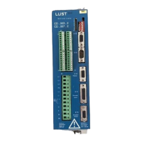
Verstärkermodul / Amplifier Module
CD_..1 / CD_..2
Nr. / No.: 181-00383
2 01.2003
Inhalt
1 Technische Daten
1.1 Geräteübersicht
1.2 Leistungsdaten
1.3 Geräteabmessungen
1.4 Einsatzbereich,
bestimmungsgemäße
Verwendung
1.5 Konformität, Normen
2 Sicherheitshinweise
2.1 Sicherheitssymbole
2.2 Achtungshinweis
2.3 Arbeitssicherheitshinweise
3 Transport
3.1 Verpackung
3.2 Auslieferungszustand
3.3 Empfindlichkeit
3.4 Zwischenlagerung
3.5 Lieferumfang
4 Aufbau und Wirkungsweise
4.1 Prinzipieller Aufbau
4.2 Wirkungsweise
4.3 Wichtige Merkmale
4.4 Prinzipschaltbild des
Regelkreises
5 Projektierungshinweise
5.1 Elektrische Installation
5.2 Schaltgeräte
5.3 Leitungsverlegung, Erdung
EMV-gerechte Verkabelung
5.4 Geräteauswahl
5.5 Endstufenschaltfrequenz
5.6 Gerätemontage
5.7 Geberkabel
5.8 Motorzuleitung
5.9 Motorschutz
5.10 Motor Haltebremse
5.11 Bohrmaße
6 Elektrische Anschlüsse
6.1 Leistungsanschlüsse X 1
6.2 Steueranschlüsse
6.3 Motorgeber X11
6.4 Encoderausgang X 13
6.5 Kommunikationsschnittstellen
6.6 Anlaufsperre
Contents
1 Technical data
1.1 Units
1.2 Performance data
1.3 Dimensions
1.4 Applications and
intended use
1.5 Conformity/Standards
2 Safety guidelines
2.1 Symbol for safety at work
2.2 Instructions ”Caution!”
2.3 Safety instructions for working
3 Transport
3.1 Packing
3.2 Delivery condition
3.3 Sensitivity
3.4 Storage
3.5 Items supplied
4 Construction of unit and method of
operation
4.1 Block diagram
4.2 Method of operation
4.3 Important characteristics
4.4 Block diagram of control loop
5 Planning information
5.1 Electrical installation
5.2 Switchgear
5.3 Cable routing, earthing, EMC
in cabling
5.4 Selection of unit
5.5 Output stage switching
frequency
5.6 Mounting
5.7 Sensor cable
5.8 Motor conduct
5.9 Motor protection
5.10 Motor holding brake
5.11 Drilling dimensions
6 Electrical connections
6.1 Power connections X1
6.2 Control connections
6.3 Motor sensor X11
6.4 Encoder output X13
6.5 Communication interfaces
6.6 Protection against starting