* If the impedance is less than 10 KΩ , Cs is shown on the display.
* If intend to obtain the accurate value, please test the component
into the " Pin terminals " ( 3-11, Fig. 1 ) or tested via optional
SMD tester, SMDA-22 or SMD test clip, SMDC-21.
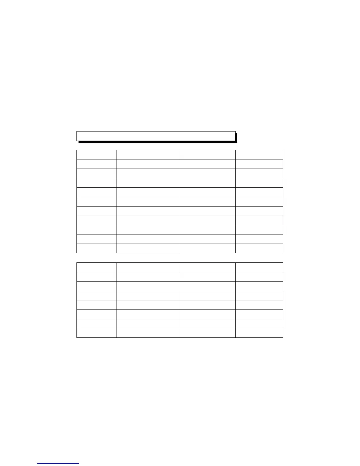
Inductance ( Lp/Ls ) : D 0.1≦
Range Accuracy Accuracy Remark
100 Hz/120 Hz 1000 Hz
20 uH ± ( 1% + 5d ) ± ( 1% + 5d ) After calibration
200 uH ± ( 1% + 5d ) ± ( 1% + 5d ) After calibration
2000 uH ± ( 0.8% + 5d ) ± ( 0.8% + 5d )
20 mH ± ( 0.5% + 5d ) ± ( 0.5% + 5d )
200 mH ± ( 0.5% + 5d ) ± ( 0.5% + 5d )
2000 mH ± ( 0.5% + 5d ) ± ( 0.5% + 5d )
20 H ± ( 0.5% + 5d ) ± ( 0.5% + 5d )
200 H ± ( 0.5% + 5d ) ± ( 0.8% + 5d )
2000 H ± ( 1% + 5d ) ------------------- After calibration
Range Accuracy Accuracy Remark
10 KHz 100 KHz
20 uH ± ( 1% + 5d ) ± ( 1% + 5d ) After calibration
200 uH ± ( 0.8% + 5d ) ± ( 0.8% + 5d ) After calibration
2000 uH ± ( 0.5% + 5d ) ± ( 0.5% + 5d )
20 mH ± ( 0.5% + 5d ) ± ( 0.5% + 5d )
200 mH ± ( 0.5% + 5d ) -------------------
2000 mH ± ( 0.5% + 5d ) -------------------
Remark :
* If the impedance is lar
* If the impedance is less than 10 KΩ , Ls is shown on the display.
* If intend to obtain the accurate value, please test the component
into the " Pin terminals " ( 3-11, Fig. 1 ) or tested via optional
SMD tester, SMDA-22 or SMD test clip, SMDC-21.
5
 Loading...