SPECIFICATION SUBMITTAL Page
Job Name:
Job Number:
Model Numbers:
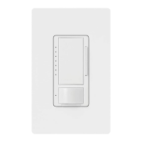
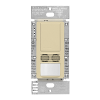
Dual Technology Switch with Occupancy Sensor
369773b 11 12.19.13
Maestro® Sensor
Wiring must comply with NECR code for wiring multiple branch circuits. Where two or more branch circuits supply
devices or equipment on the same yoke, a means to simultaneously disconnect the ungrounded conductors
supplying those devices shall be provided at the point at which the branch circuits originate.
m30
15
5
1
Occ
LRN
Fixd
Vac
Mode
Hi
Med
Low
Off
Hi
Med
Low
Min
PIR
m30
15
5
1
Occ
Lrn
Fixd
Vac
Mode
Hi
Med
Low
Off
Hi
Med
Low
Min
PIR
Black
Blue
Ground
MS-B202
1
Green
Ground
120–277 V~
50 / 60 Hz
Line/Hot
Load 2
Standard
Mechanical Switch
2,3
Black
Yellow Jumper
wire (included)
Different
color
screw
Neutral
Black-Orange
Load 1
Black-Orange
White
Line/Hot
Wiring Diagrams - Dual Circuit (MS-B202) (continued)
1
Dual Tech sensor switch can be installed in any location.
2
Mechanical switch may be wired to either circuit, and will control both. Do NOT wire mechanical switch to both circuits.
3
You may use no more than one mechanical switch with a Dual circuit Dual Tech sensor switch.
Wiring Diagram 4
3-way Installation, Two Breaker Feed Wiring: Dual Circuit (MS-B202)
NOTE: Do not use
Maestro Accessory
switches with MS-B202.
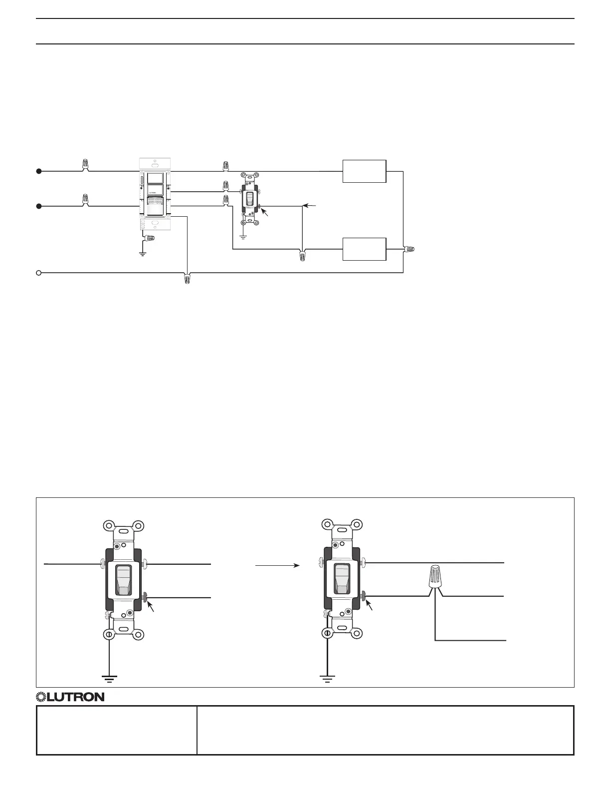
3-Way Installation
For retrofit 3-way installations the mechanical switch needs to be rewired as shown in the diagram below after wiring the
Dual Tech sensor switch. Otherwise the 3-way installation will not work as expected. Single-Pole mechanical switches may
also be used in a 3-way with MS-B102 and MS-B202 models.
m30
15
5
1
Occ
LRN
Fixd
Vac
Mode
Hi
Med
Low
Off
Hi
Med
Low
Min
PIR
m30
15
5
1
Hi
Med
Low
Off
Occ
Lrn
Fixd
Vac
Mode
Hi
Med
Low
Min
PIR
Traditional 3-way Mechanical Switch Wiring
Ground
Traveler Traveler
Common
1. Connect Ground: Ensure the bare copper or green ground wire from the wallbox is connected to the green ground screw of the mechanical
switch.
2. Tag circuit Common: Your 3-way mechanical switch should have three screw terminals, two of the same color, and one of a different color.
Tag the wire that is connected to the screw terminal of a different color.
3. Identify the wire that matches the color of the wire you connected to the blue wire of the MaestroR Dual Technology Occupancy Sensor
Switch. Connect this wire to one of the two terminals of the same color.
4. Combine the tagged wire, the remaining wire and yellow jumper wire (included) using a wire connector. Connect the other end of jumper
wire to the different color screw.
m30
15
5
1
Occ
LRN
Fixd
Vac
Mode
Hi
Med
Low
Off
Hi
Med
Low
Min
PIR
m30
15
5
1
Hi
Med
Low
Off
Occ
Lrn
Fixd
Vac
Mode
Hi
Med
Low
Min
PIR
Yellow Jumper
wire (included)
Traveler (to Blue wire)
Tagged Wire
(Common)
Traveler
(to Black OR Black-Orange wire)
Ground
Different
color
screw
3-Way Mechanical Switch Wiring With Dual Tech Sensor Switch
Different
color
screw
Rewire to
 Loading...