Do you have a question about the Lutron Electronics Maestro MS-OPS2 1 Series and is the answer not in the manual?
Details passive infrared sensors, field-of-view, coverage, and operational modes.
Lists available model numbers, including color/finish codes and specific regional variants.
Covers UL listing and NOM certification for Maestro models.
Specifies voltage and frequency ratings for device operation.
Highlights features like lens durability, ambient light detection, and adaptive switching.
Details operating temperature and humidity range for the device.
Provides information on the 5-year limited warranty and where to find details.
Lists notes on GFI circuits, dimmer models, and Lutron customer assistance.
Explains switching technologies and XCT sensing for enhanced performance.
Describes how the sensor adjusts to natural light levels for automatic operation.
Details available modes like Auto-ON/Auto-OFF and Manual-ON/Auto-OFF.
Lists available timeout durations from 1 to 30 minutes.
Allows adjustment between high and low sensitivity settings.
Explains occupancy and vacancy auto-on configurations.
Configures behavior when the switch is manually turned off while occupied.
Covers crush/tamper resistance and smart ambient light adjustment.
Details XCT technology, switching, and manual off-while-occupied settings.
Specifies the default timeout duration for various models.
Explains line-of-sight requirements and environmental factors affecting performance.
Defines "Major motion" and "Minor motion" for clarity.
Illustrates major and minor motion coverage areas and beam patterns.
Provides physical measurements of the sensor switch in inches and millimeters.
Details how to prepare controls for ganging in a wallbox.
Lists components like wallbox, adapter, and mounting screws.
Explains the function of the tapswitch and the sensor lens indicator LED.
Details wiring for single location installation with a neutral connection.
Details wiring for single location installation without a neutral connection.
Details wiring for single location installation with a neutral connection.
Details wiring for single location installation without a neutral connection.
Shows 3-way wiring with neutral for specific models.
Shows 3-way wiring without neutral for specific models.
Continues details for 3-way wiring without neutral for specific models.
Details 3-way wiring with neutral for 277V applications.
Details 3-way wiring without neutral for 277V applications.
Continues details for 3-way wiring without neutral for 277V applications.
Shows multi-location wiring with neutral for 120V systems.
Shows multi-location wiring without neutral for 120V systems.
Details multi-location wiring with neutral for 277V systems.
Details multi-location wiring without neutral for 277V systems.
Shows single location wiring with neutral for 120-277V systems.
Shows single location wiring without neutral for 120-277V systems.
Details 3-way wiring with neutral for 120V systems.
Details 3-way wiring without neutral for 120V systems.
Continues details for 3-way wiring without neutral for 120V systems.
Details 3-way wiring with neutral for 277V systems.
Details 3-way wiring without neutral for 277V systems.
Continues details for 3-way wiring without neutral for 277V systems.
Shows multi-location wiring with neutral for 120V systems.
Shows multi-location wiring without neutral for 120V systems.
Details multi-location wiring with neutral for 277V systems.
Details multi-location wiring without neutral for 277V systems.
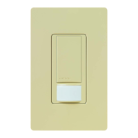
Lists available gloss finish colors for the switches.
Lists available satin finish colors for the switches.
The Lutron Maestro occupancy sensor switch integrates a Maestro switch with a passive infrared occupancy or vacancy sensor. This device detects heat from moving occupants within a space to determine if it is occupied. Based on this feedback, the occupancy sensor switch adjusts the connected load accordingly.
The Maestro sensor switch is designed to provide automated lighting control based on occupancy. It uses passive infrared sensors with Lutron's exclusive XCT Technology for precise fine motion detection, ensuring that lights remain on when a room is occupied and do not turn on falsely when vacant. The sensor offers a wide 180° field-of-view, covering up to 900 ft² (81 m²) for major motion and 400 ft² (36 m²) for minor motion.
The occupancy version of the sensor switch can be configured for either Auto-ON/Auto-OFF operation, where lights turn on automatically upon entry and off upon vacancy, or Manual-ON/Auto-OFF, requiring manual activation but automatic deactivation. A vacancy-only version is also available, specifically designed to meet CA Title 24 requirements, operating solely in Manual-ON/Auto-OFF mode.
The device supports a variety of load types, including incandescent, halogen, ELV, MLV, CFL, LED, magnetic fluorescent, electronic fluorescent, and fan loads. It features adjustable timeout options, allowing users to select between 1, 5, 15, or 30 minutes for lights to remain on after the last detected motion. Sensitivity can also be adjusted between high (default) and low settings to fine-tune motion detection.
For enhanced energy savings, the sensor switch includes ambient light detection, ensuring that lights only turn on if natural light in the room is low. The "Smart" ambient light threshold feature allows the device to learn and adapt to the user's preferred lighting levels over time. Additionally, presets for ambient light detection (high, medium, low, and disabled) are available.
The device incorporates advanced switching features to maximize relay life. It utilizes standard zero-cross switching, which activates at the point of minimum energy on the AC power curve. Adaptive zero-cross switching further enhances relay life by actively adapting to variations in relay timing. Lutron's patented Softswitch circuit eliminates arcing at mechanical contacts during switching, extending relay life to an average of 1,000,000 cycles for resistive, capacitive, or inductive sources.
The Maestro sensor switch offers flexible configuration options to suit various user preferences and room types. In occupancy mode, users can choose between automatic or manual activation. For vacancy-only operation, manual activation is the standard.
A key feature is the "Manual Off-While-Occupied" option, which can be enabled or disabled. When enabled, if the lights are manually turned off while the room is occupied, they will not automatically turn back on in response to motion. This is particularly useful in settings like conference rooms or classrooms during presentations, where motion should not trigger the lights. Once the room is vacated, the Auto-ON feature returns to normal operation after the timeout period. If disabled, the Auto-ON feature will return to normal operation after 25 seconds, allowing lights to turn on automatically upon re-entry even if they were manually turned off.
The device's XCT Technology ensures reliable fine motion detection, preventing lights from turning off prematurely while a room is occupied. This advanced sensing capability is crucial for maintaining comfort and convenience in occupied spaces.
For multi-location installations, the Maestro sensor switch can be integrated with standard mechanical 3-way switches or Lutron companion switches (MA-AS, MSC-AS, MA-AS-277, or MSC-AS-277). This allows control of the load from more than two locations, with the ability to connect up to nine companion switches.
The Maestro sensor switch is designed for durability and ease of maintenance. It features a crush/tamper-resistant lens, protecting the sensor from accidental damage and ensuring long-term performance.
The device is backed by a 5-Year Limited Warranty, providing assurance of its quality and reliability. Detailed warranty information is available online for user reference.
For installations in wallboxes with other controls, specific instructions are provided for removing inside fins (for UMS-OPS6M-DV and UMS-VPS6M-DV models only) to ensure proper fit and ganging. Users are advised not to remove outside fins on end-of-gang controls.
Wiring diagrams are comprehensively provided for various installation scenarios, including single-location and multi-location setups, with and without neutral connections, and for different voltage requirements (120 V~ and 277 V~). These diagrams guide electricians through proper installation, ensuring optimal performance and safety.
The device's design also considers retrofit and replacement applications, offering clear guidance on neutral and ground wire connections. For instance, if a neutral connection is available, the green sleeve should be removed, and the white wire connected to neutral. If a neutral connection is not available, the green-sleeved wire should be connected to ground. A ground or neutral wire is essential for the product's function, and a licensed electrician should be consulted if neither is present.
The Sensor LED, located behind the lens, provides visual feedback, pulsing during configuration of custom settings and when in Test mode, which aids in troubleshooting and setup.
| Brand | Lutron Electronics |
|---|---|
| Model | Maestro MS-OPS2 1 Series |
| Category | Security Sensors |
| Language | English |