HOW TO REMOVE THE SHADE:
If it becomes necessary to remove the shade for adjustments
or for any other reason, use the frosting knife or the fl at-blade
screwdriver as shown.
a. Insert the tool between the mandrel and the bracket.
b. Push the retaining spring (inside the bracket) aside by applying
pressure on the tool handle toward the center of the shade.
c. With the shade released, withdraw the tool, then the shade.
d. Repeat steps a., b., and c. at the other end of the shade.
?
Chassis Installation & Setup Guide
)Lutron and PALLADIOM are trademarks of Lutron Electronics Co., Inc., registered in the U.S. and other countries
Lutron Electronics Co., Inc. 7200 Suter Road, Coopersburg, PA 18036-1299, U.S.A.
11/2018
P/N 045657 Rev. B
SHADING SYSTEM
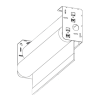
Connect the Wire Harness to the EDU
a. Position the drive end of the shade near the mounted drive-end bracket, and rotate the shade
toward you so you can see the EDU connector on the back side of the drive mandrel.
b. Plug the wire harness (installed in Section
1
) into the EDU connector (i), ensuring it is fully
inserted (ii), then rotate the shade back into the position shown (iii).
FINAL ADJUSTMENTS:
5
AESTHETIC TRIM:
6
1⁄ 2 in (12 mm)
1⁄ 2 in - 5⁄ 8 in
(12 mm - 16 mm)
a. b.
i ii iii
Idler
Mandrel
Idler
Bracket
Spring
Push
Release
* NOTE: The idler is spring-loaded, with 1⁄ 8 in (3 mm) of travel to allow for installation
tolerance. At the correct bracket-to-bracket distance, the idler will be fully
compressed. Extension of the idler indicates increased bracket-to-bracket distance,
and results in a larger light gap at the idler side of the shade. Refer to section
5
for
more information.
Drive
Mandrel
Wire Harness
Drive
Bracket
Idler
Bracket
Drive-end Bracket
(wall mount shown)
EDU
Connector
EDU
Connector
1⁄ 8 in (3 mm)
adjustment
1⁄ 8 in (3 mm)
adjustment
Rotate the entire shade to
view the EDU Connector
Loosen or remove screws; adjust
and re-tighten (end bracket shown).
Jamb
End
Center
Backside View
INSTALL THE SHADE:
IMPORTANT: The steps in this section must be performed by two people, with one person supporting each end of the shade. If the brackets are mounted in a location that cannot be reached
when standing on the fl oor, two ladders are also required. It is recommended that all steps are reviewed by both installers before proceeding.
3
Hang the Shade in the Mounting Brackets (Idler End First)
a. Holding both ends of the shade in alignment with the brackets, aim the idler* mandrel at
the bracket-shade interface opening as shown and insert.
b. Push the mandrel into the bracket until it seats with a click.
c. Repeat steps a. and b. at the drive end of the shade.
d. After both ends of the shade are pushed in and seated, pull back on the shade to confi rm it
is securely locked into both brackets.
About Light Gaps
Light gaps are symmetrical at 1⁄ 2 in (12 mm), when the
bracket-to-bracket distance is correct. As noted in section
3
, extension of the spring-loaded idler may add up to
1⁄ 8 in (3 mm) of light gap on the idler end of the shade.
Install the Bracket Covers (end and center only)
Position a bracket cover on the mounting surface as shown, and
slide it over the bracket foot to conceal the fastener heads. Repeat
for remaining bracket(s).
Adjust Bracket Positions
If light gaps are not equal, or if telescoping * is
observed, remove the shade and adjust mounting
bracket positions to correct. Ensure the moving shade
does not rub on any part of the bracket.
Rotate the Finishing Rings
Rotate the fi nishing ring of each bracket to conceal the bracket-
shade interface opening. The ring features detents that will hold it
in a specifi c position for best concealment.
* For additional information on telescoping, please see Application Note #14 at www.lutron.com
Install one or two shims (each adds 1⁄ 16 in [1.6 mm]).
Using more than two shims will impact bracket aesthetic.
POWER-UP AND ADJUST LIMITS:
POWER: Turn on the supply circuit breaker to energize the power supply and power up the
shade. The shade’s LED indicator will fl ash a multi-color sequence upon power-up. For a complete
guide to LED signals, see: www.lutron.com/TechnicalDocumentLibrary/Sivoia QS Shades.html
LIMITS: Default open and close limits are set at the factory based on the window size entered
with the original order. If adjustment is necessary, follow the steps below to set new limits.
Setting the Open Limit
a. Tap the round button. The green LED will turn on.
b. Use the arrow buttons to jog the shade to the
desired open-limit position.
c. Press and hold the round button until the green LED
fl ashes. The open limit is now set and stored.
Setting the Close Limit
a. Tap the square button. The green LED will turn on.
b. Use the arrow buttons to jog the shade to the
desired close-limit position.
c. Press and hold the square button until the green
LED fl ashes. The close limit is now set and stored.
Verify Operation
After limits are set, run the shade up and down several times to verify smooth,
unobstructed operation and straight roll-up.
b.
b.
a.
a.
c.
c.
TAP
TAP
HOLD
HOLD
JOG
JOG
4
 Loading...