6
P/N 032498h
Step 1: Identify the HVAC Equipment and Confirm Device Installation
(continued)
Confirm Device Installation
(continued)
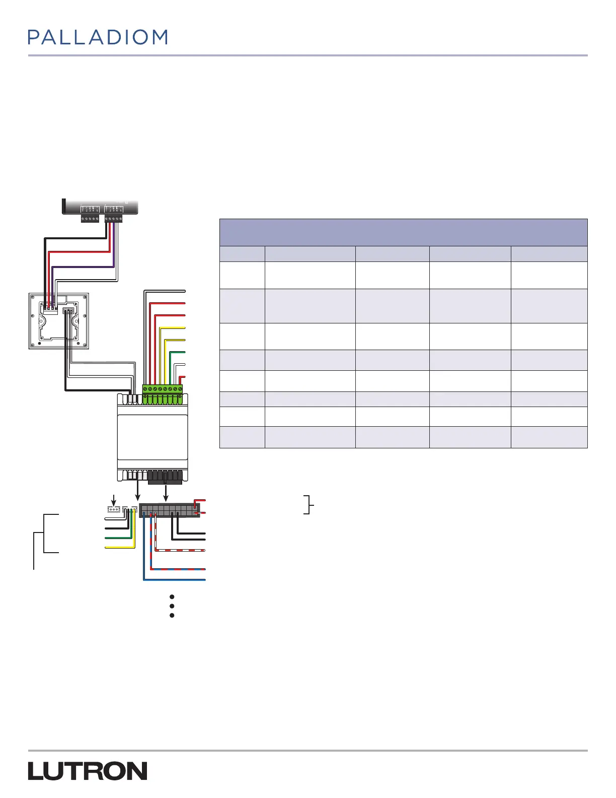
If connecting the Palladiom Thermostat to the SMC55-HWQS, they must be connected over the HVAC controller communication
link. Refer to Figure 1 for the wiring required to install the SMC55-HWQS with the thermostat. For hardware installation and
wiring details refer to the HomeWorks QS Thermostat Installation Guide (P/N 043495) at www.lutron.com.
43
G
5
AO
#5
#6
#7
#8
#9
#10
#11
#12
43
21
HomeWorks QS
Palladiom HVAC
Controller
HomeWorks
QS Palladiom
thermostat
QS Link
Power and
communication
Gray (G) Com
Common
V+
MUX
_
Black
Black
Orange / White (connect to black common wire for additional HVAC controllers only. This connection will set
the Modbus address to 02)
Blue / Red (FCU changeover sensor or radiant floor slab sensor)
Blue (remote temperature sensor)
White (+) MUX
Black (−) _
Optional signal wires
HomeWorks QS
processor
Red (R
H
) Heat transformer
Gray /Red (C) Common
HVAC Controller Power (from HVAC system transformers)
24 V~ IEC / SELV / PELV / NECR Class 2
Wire harness for 0–10V-
valves and fan controls
Not used
White (heat)
Black (common)
Green (fan)
Yellow (cool)
Figure 1: SMC55-HWQS Setup for Configuration Using a Thermostat
Relay Terminals
SPST(NO) 1 A 24 V~ maximum relays
Terminal Conventional Heat Pump
1
Fan Coil Unit Radiant Floor
2
#5 Heat stage 1 (W
1
)
Changeover heat
pump valve (O/B)
Hot valve (H
VALVE
) Heat stage 1 (W
1
)
#6
Heating stage1
transformer (R
H
)
Heating
transformer(R
H
)
Heat valve
transformer(R
H
) or
Valve transformer(R)
Heat stage 1
transformer (R
1
)
#7
Cooling / compressor
transformer (R
C
)
Cooling
transformer(R
C
)
Fan transformer (R
FAN
) –
#8 Compressor stage1 (Y
1
)
Compressor
stage 1(Y
1
)
Fan high (G
3
) –
#9
Compressor stage2
(Y
2
)
1
Compressor
stage 1(Y
2
)
Fan medium (G
2
) –
#10 Fan (G) Fan (G) Fan low (G
1
) –
#11 Heat stage 2 (W
2
)
1
Auxiliary heat (AUX) Cold valve (C
VALVE
) –
#12
Heating stage2
transformer (R
H2
)
1
Auxiliary heat
transformer(R
AUX
)
Cold valve
transformer (R
C
)
–
1
Included with SMC55-RESI version 7302 or newer and HomeWorks Palladiom Thermostat version 1.10 or newer.
2
Included with SMC55-HWQS version 7420 or newer and HomeWorks Palladiom Thermostat version 1.10 or newer.