EasyManua.ls Logo

Lutron Electronics RadioRA3 - User Manual

Lutron Electronics RadioRA3
24 pages
To Next Page IconTo Next Page
Loading...
English
Installation Instructions
Please Read Before Installing
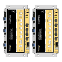
Product Overview
Status LED
Green = Normal operation
Blue = Firmware upgrade in process
Red = Error
Program Button
Used to factory reset processor
and to associate into a system
This wireless processor works with RadioRA 3 compatible wireless devices, including Sunnata
dimmers/switches/keypads, Maestro dimmers/switches, seeTouch keypads, Pico controls,
Radio Powr Savr sensors, RF dimmer and switch modules, plug-in dimmers and switches, and
Triathlon and Sivoia QS wireless shades. Other products may also be compatible; see individual
product spec sheets for details on system compatibility.
This wireless processor must be powered by an IEEE 802.3af 2003 or 802.3at 2009 compliant
LPS / SELV PoE or PoE+ power supply.
P/N 044377 Rev. A
07/2021
Wireless Processor
RR-PROC3
48 V- 100 mA

Questions and Answers:

Lutron Electronics RadioRA3 Specifications

General IconGeneral
BrandLutron Electronics
ModelRadioRA3
CategoryComputer Hardware
LanguageEnglish

Summary

Product Overview

Status LED

Explains LED colors for normal operation, firmware upgrade in process, and error states.

Program Button

Describes its function for factory reset and system association.

Additional Components

Included in RR-PROC3-KIT

Lists shelf-mount adapter, PoE injector, region-specific plugs, and Ethernet cables.

Included in RR-PROC3-CW

Lists recess-mount adapter and junction box mount adapter.

Tools Required

Tools You May Need

Lists necessary tools like ladder, hole saw, drill, Philips head screwdriver, and pencil.

Step 1 - Choose a Location to Install

Distances for Wireless Devices

Specifies maximum distances for device communication and repeater placement for optimal reliability.

Step 4 a - Installation using the Recess-Mount Adapter

Ceiling Installation

Details the process for recess-mount adapter installation in a ceiling.

Wall Installation

Details the process for recess-mount adapter installation in a wall.

Step 4 b - Installation using the Junction Box Mount Adapter

Ceiling Installation

Details the process for junction box mount adapter installation in a ceiling.

Wall Installation

Details the process for junction box mount adapter installation in a wall.

Step 4 c - Installation using the Shelf-Mount Adapter

Horizontal Mounting

Explains shelf-mount adapter installation horizontally on a level surface.

Vertical Mounting

Explains shelf-mount adapter installation vertically on a wall.

Step 5 - System Setup

LED Diagnostics

Explains processor and PoE injector LED patterns for status and troubleshooting.

Troubleshooting

Provides common symptoms and their probable causes for system issues.

FCC;IC;IFT Information

Compliance and Operation Conditions

Details FCC/IC compliance rules, interference, and radio frequency exposure limits.

Related product manuals