Basic Wiring and Setup Guide
Sivoia® QS Wireless
English
Tools required:
Wire Cutter/Stripper
Included items required for Basic Wiring and Setup:
(1) 4-pin terminal block
(1) Screwdriver
WARNING: Risk of electric shock. Lock MCB
(supply breaker) in the OFF position, or remove
fuse, before wiring to terminal block. Failure to do
so, could result in death or serious injury.
•
This Sivoia QS Basic Wiring and Setup Guide is a
complement to the Chassis Installation Guide enclosed
for the specific shade or drape type ordered. This guide
describes the basic wiring and setup requirements
for basic operation and to verify the shade or drape
is functioning.
•
Codes: Install in accordance with all local and national
electrical codes.
•
Environment: Ambient operating temperature:
32 °F to 104 °F (0 °C to 40 °C), 0 to 90% humidity,
non-condensing. Indoor use only.
Connect terminal blocks
Plug 4-pin terminal block on cable to the shade or drape drive
terminal block.
2.1
2
Note: Arrange
wires in a location
that prevents them
from interfering
with moving shade
or drape.
N/C
N/C
24 V (Pin 2) (RED)
Common (Pin 1) (BLACK)
}
To EDU
Connector
Wire 4-pin terminal block (provided) to cable using the included
screwdriver. Tighten screws securely on the exposed wire.
Leave 1/16 in (2 mm) of exposed copper to ensure insulation is
not pinched.
1.3
Roller 100
Drive shown
1/16 in
(2 mm)
(1) Wireless receiver
(1) Wireless receiver mounting clip
(2) Wireless receiver mounting screws
(2) Antenna clips
The specific location of the receiver varies depending on the type of
installation. Refer to the appropriate figures for your application; Wall
Mount, Ceiling Mount , Fascia Mount, Pocket Mount or Drapery Track.
The receiver can either be mounted with the screws or the mounting
clip, which are both provided.
(3) 4 in cable ties
Fig. C
Wall Mount
Fig. D
Ceiling Mount
Antenna Clip
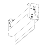
Option 2: Screw Mounting
the Receiver in a Fascia or
Pocket enclosure Refer to Fig. E
and Fig. F for recommended mounting
locations.
1. Insert the screws through the
receiver and into the top of the back
wall of the pocket or fascia enclosure.
Note: If the installation does not permit
the use of screws, refer to Option 3
(Clip mounting the Receiver).
2. Remove the paper liner from the
self-adhesive strip on the antenna clips.
3. Attach the antenna clips in a location
that allows a section of the antenna to
be exposed at the bottom of the fascia
or pocket enclosure. The clips can also
be attached using a screw appropriate
for the mounting surface
4. Insert the antenna into both antenna
clips.
Note: If top/back cover is not being
used with the fascia mount installation,
mount antenna clips to the wall below
the shade tube.
Wire 4-pin terminal block
Strip 2 in (51 mm) of outer jacket off cable coming from the wall.
1.1
1
1/4 in
(6 mm)
2 in
(51 mm)
Strip 1/4 in (6 mm) insulation off each individual wire.
1.2
Connect wireless receiver
Plug in the wireless receiver to the shade or drape drive.
3.1
3
Fig. E
Fascia Mount
Fig. F
Pocket Mount
Mounting the wireless receiver
The receiver can be mounted with the antenna positioned adjacent to the
receiver as shown in Fig. A. It can also be positioned, as shown in Fig. B,
for use in a fascia or pocket installation. This ensures optimum range in
a fascia or pocket application, by allowing a section of the antenna to be
located outside the enclosure.
4
Fig. A
Fig. B
Antenna
Receiver
Receiver
Antenna
Antenna section located
outside the enclosure
Fig. G
Drapery Mount
(Windows side view of
drapery track shown)
Option 1: Screw Mounting
the Receiver to the Wall
or Ceiling Refer to Fig. C and
Fig. D for recommended
mounting locations.
1. Insert the screws through the
mounting holes in the receiver and
antenna clips and attach to the wall
or ceiling.
2. Snap the antenna into both
antenna clips.
Option 3: Clip Mounting the
Receiver to a Wall, Ceiling
or Drapery Track Refer to Fig.
C, Fig. D and Fig. G for recommended
mounting locations.
1. Remove the adhesive liner from the
antenna mounting clip and attach to
the back of the wireless receiver.
2. Snap the receiver into the
receiver clip.
3. Remove the adhesive liner on the
receiver clip and attach to the wall,
ceiling or drapery track.
4. Snap the antenna into both
antenna clips.
Antenna clip
Antenna Clips
Receiver clip
Receiver
Antenna Clip
Antenna
Receiver
Antenna
Receiver
Mounting the wireless receiver (continued)
4
Mounting the wireless receiver (continued)
4
Choose one of the following four mounting options that is
appropriate for your application.