This sheet contains basic installation and setup instructions. There are additional topics covered in
greater detail, in the full version of the manual for this thermostat. The full PDF manual can be
downloaded at http://www.luxproducts.com. Click on SUPPORT, then INSTRUCTION MANUALS. Many
thermostat models have lower case “revision” letters after the model name (i.e. TX1500Ua). Please
choose the manual that exactly matches the model number shown on your particular thermostat.
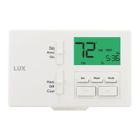
The front panel buttons can be locked out to prevent unauthorized tampering of the set temperature and
other settings. Neither the System Mode or Fan Mode slide switches are locked out, and when the
Keypad Lockout is active, there will be a padlock icon shown in the display screen.
To lock or unlock the keypad buttons, first select either HEAT or COOL on the System Mode switch, and
press the following four-button sequence: NEXT, NEXT, NEXT, HOLD.
By default, this thermostat has 4 separate program periods for both Heat and Cool modes, they are:
MORN, DAY, EVE, and NITE. Each period ends at the start time of the next upcoming period. The Heat
temperature programs are set while the mode switch is in the HEAT position, and the Cool temperature
programs are set while the mode switch is in COOL.
NOTE: If the thermostat is configured to use only 2 periods per day (instead of the factory default of 4
periods per day), the thermostat will only use the DAY and NITE period designations. The MORN and
EVE periods will not be used or visible on the screen.
TO SET A TEMPERATURE PROGRAM: Choose either HEAT or COOL mode, and press the SET button.
Programming will start with PROG position. Use UP or DOWN to adjust the start time for the first
period, and then press the NEXT button to advance. Use UP or DOWN to adjust the set temperature for
the first period, and then press the NEXT button to advance. Now adjust the start time and set
temperature for the second period, pressing NEXT after each item to advance. Continue with these
same steps to adjust the start times and set temperatures for the third and fourth periods (if present).
When the last period is finished for each day (or group of days), the thermostat will advance forward
into the next day (or group of days).
When you are complete, you can press the SET button to save your changes and return back to the
normal run mode.
NOTE: If a temperature program routine is not desired, you may change ITEM #02 in the Setup Options
to “3” for manual non-programmable.
Basic operation of your heating or cooling system can be obtained by selecting HEAT or COOL on the
System Mode switch, and using UP or DOWN to adjust the temperature. To maintain a single fixed
temperature, you can use the HOLD button. If there is a padlock present on the display screen, the
keypad lockout feature is enabled (both of the mode slide switches are still functional).
1) If the wiring diagrams do not clearly represent or match your system, please refer to “TECHNICAL
ASSISTANCE” below, and contact us before
removing any of your existing thermostat wires.
2) All of the DASHED wires shown in the wiring diagrams are either optional, or their usage depends
upon your specific system type (EXAMPLE: Diagram #1 shows the fan wire as optional. This does not
infer that your system does not have a fan, only that there may not be a wire for it).
3) The terminal letters shown in black represent typical wiring usage. The terminal letters shown in
gray represent other possible wiring letter designations that you might see on your particular brand
and model of thermostat.
4) The optional “C” terminal is used for powering the thermostat by the 24 volts supplied by your
heating/cooling system, using the System Common wire. This can be used alone, or in addition to
installing batteries as a backup. NOTE: when using batteries, connecting the System Common wire
to the thermostat is not necessary for heating and cooling to function properly.
5) If your old thermostat has BOTH an “O” wire and a “B” wire present
, then “B” is likely a System
Common (power wire) and can either be connected to the “C” terminal, or taped off and unused.
Connecting a System Common wire to this thermostat’s “B/O” terminal will damage the thermostat,
and also your heating and cooling system equipment.
6) If your existing thermostat connections contain a wire labeled as “W2”, “AUX”, “E”, or “X2”, this
would indicate that you have additional heating stages present. This is a single-stage thermostat,
and cannot accomodate any of these system components. You will need to select a different model.
7) If replacing an old thermostat that has a mechanical time clock on the front panel, there may be TWO
wires labeled as “C” for the clock power. Do not connect either of them to this thermostat.
If you have any problems installing or using this thermostat, please carefully and thoroughly review the
instruction manual. If you still require assistance, please contact our Technical Assistance department
at 856-234-8803 during regular business hours between 8:00AM and 4:30PM Eastern Time, Monday
through Friday. You can also receive technical assistance online anytime day or night at
http://www.luxproducts.com. Our website offers you troubleshooting guides, answers to the most
common technical questions, and also permits you to email your questions to our technical support staff
at your convenience.
KEYPAD LOCKOUT:
TECHNICAL ASSISTANCE:
WIRING DIAGRAM NOTES:
5357253574
TEMPERATURE PROGRAMMING:
DOWNLOAD FULL INSTRUCTION MANUAL FROM OUR WEBSITE: BASIC HEATING AND COOLING OPERATION:
2 / 3 / 4 WIRES
CONVENTIONAL, NON HEAT PUMP
1-STAGE, HEAT ONLY
(INCLUDING MILLIVOLT)
NOTE: THE BLACK TERMINAL LETTERS ARE TYPICAL,
GRAY TERMINAL LETTERS ARE BRAND SPECIFIC
W1 4W
X
FG
RH VR
Factory
RH-RC
Jumper
Wire
Installed
#1
C
FAN
24V HEAT
TRANSFORMER
OPTIONAL
SYSTEM COMMON
HEATER
Y1 6Y
A/C
UNIT
2 / 3 / 4 WIRES
CONVENTIONAL, NON HEAT PUMP
1-STAGE, COOL ONLY
NOTE: THE BLACK TERMINAL LETTERS ARE TYPICAL,
GRAY TERMINAL LETTERS ARE BRAND SPECIFIC
X
FG
Factory
RH-RC
Jumper
Wire
Installed
#2
C
FAN
OPTIONAL
SYSTEM COMMON
RC VR
24V COOL
TRANSFORMER
Y1 6Y
A/C
UNIT
3 / 4 / 5 WIRES
CONVENTIONAL, NON HEAT PUMP
1-STAGE HEAT AND 1-STAGE COOL
NOTE: THE BLACK TERMINAL LETTERS ARE TYPICAL,
GRAY TERMINAL LETTERS ARE BRAND SPECIFIC
W1 4W
X
FG
RH VR
Factory
RH-RC
Jumper
Wire
Installed
#3
C
FAN
24V
TRANSFORMER
OPTIONAL
SYSTEM COMMON
HEATER
Y1 6Y
A/C
UNIT
4 / 5 / 6 WIRES
CONVENTIONAL, NON HEAT PUMP
1-HEAT / 1-COOL, WITH TWO-TRANSFORMERS
NOTE: THE BLACK TERMINAL LETTERS ARE TYPICAL,
GRAY TERMINAL LETTERS ARE BRAND SPECIFIC
W1 4W
X
FG
R VRH
REMOVE
Factory
RH-RC
Jumper
Wire
#4
C
FAN
24V HEAT
TRANSFORMER
OPTIONAL
SYSTEM COMMON
HEATER
R VRC
24V COOL
TRANSFORMER
B*
Y1 6Y
HEAT
PUMP
3 / 4 / 5 WIRES
HEAT PUMP SYSTEMS
1-HEAT / 1-COOL ONLY,
WITH NO AUXILIARY / EMERG. HEAT
NOTE: THE BLACK TERMINAL LETTERS ARE TYPICAL,
GRAY TERMINAL LETTERS ARE BRAND SPECIFIC
X
FG
B*
Factory
RH-RC
Jumper
Wire
Installed
For Heat-Pumps
ONLY, Add
Second
Jumper Wire
(Supplied)
#5
C
FAN
OPTIONAL
SYSTEM COMMON
O
REVERSING
VALVE
RC VR
24V
TRANSFORMER
* Heat-Pump: if “O” and “B” are both present,
install old “B” wire onto “C” terminal.
Esta hoja contiene las instrucciones básicas de instalación y configuración. Hay otros temas que se tratan con
mayor detalle, en la versión completa del manual para este termostato. El manual completo en PDF se puede
descargar en http://www.luxproducts.com. Haga clic en SUPPORT (asistencia) y luego en INSTRUCTION
MANUALS (manuales de instrucciones). Muchos modelos de termostatos tienen letras de “revisión” en
minúscula después del nombre del modelo (por ejemplo, TX1500Ua). Por favor, elija el manual que coincida
exactamente con el número de modelo que aparece en su termostato en particular.
Los botones del panel delantero se pueden bloquear para evitar la manipulación no autorizada de la
temperatura de ajuste y otros parámetros. Ni el interruptor System Mode (modos del sistema) o Fan Mode
(modos del ventilador) se bloquean, y cuando el bloqueo del teclado numérico está activo, habrá un icono de
candado que se muestra en la pantalla.
Para bloquear o desbloquear los botones del teclado numérico, seleccione HEAT (calefacción) o COOL
(refrigeración) en el interruptor System Mode (modos del sistema) y pulse la siguiente secuencia de cuatro
botones: NEXT, NEXT, NEXT, HOLD.
En forma predeterminada, este termostato tiene 4 períodos de programas distintos tanto para el modo Heat
(calefacción) como para el modo Cool (refrigeración): MORN, DAY, EVE y NITE (MAÑANA, DÍA, TARDE y NOCHE).
Cada periodo termina a la hora en que comienza el siguiente. Los programas de temperatura de calefacción se
establecen cuando el selector de modos está en la posición HEAT, y los programas de temperatura de
refrigeración se establecen cuando el selector de modo está en COOL.
NOTA: Si el termostato está configurado para usar solo 2 períodos por día (en lugar del valor predeterminado
de fábrica de 4 períodos por día), el termostato únicamente usará las designaciones de período DAY (día) y
NITE (noche). Los períodos MORN (mañana) y EVE (tarde) no se usará ni se verán en la pantalla.
PARA DEFINIR UN PROGRAMA DE TEMPERATURA: Elija el modo HEAT (calefacción) o COOL (refrigeración) y
pulse el botón SET (configurar). La programación se iniciará con la posición PROG. Use UP (arriba) o DOWN
(abajo) para ajustar la hora de inicio del primer período y luego presione el botón NEXT (siguiente) para
avanzar. Use UP (arriba) o DOWN (abajo) para ajustar la temperatura para el primer período y luego presione el
botón NEXT (siguiente) para avanzar. Ahora, ajuste la hora de inicio y la temperatura para el segundo periodo,
presione NEXT luego de cada elemento para continuar. Repita estos mismos pasos para ajustar las horas de
inicio y establecer temperaturas para el tercer y cuarto períodos (si están presentes).
Cuando el último período terminó para cada día (o grupo de días), el termostato avanzará al siguiente día (o
grupo de días).
Cuando haya finalizado, puede pulsar el botón SET (configurar) para guardar los cambios y volver al modo de
funcionamiento normal.
NOTA: Si no se desea una rutina de programa de temperatura, es posible cambiar el ELEMENTO N.° 02 en las
Setup Options (opciones de configuración) a “3” para el modo manual no programable.
El funcionamiento básico de su sistema de calefacción o refrigeración se puede activar mediante la selección
de HEAT (calefacción) o COOL (refrigeración) que están en el interruptor System Mode (Modos del sistema) y
empleando UP (arriba) o DOWN (abajo) para ajustar la temperatura. Para mantener una única temperatura fija,
puede utilizar el botón HOLD (mantener). Si hay un candado en la pantalla de visualización, la función de
bloqueo del teclado numérico está activada (ambos interruptores deslizantes de modo todavía funcionan).
1) Si los diagramas de cableado no representan o no coincide claramente con su sistema, por favor consulte la
sección “ASISTENCIA TÉCNICA” a continuación y comuníquese con nosotros antes
de retirar cualquier cable
de su termostato actual.
2) Todos los cables marcados con LÍNEAS PUNTEADAS que se muestran en los diagramas de cableado son
opcionales o su uso depende del tipo de su sistema específico (EJEMPLO: El diagrama N.° 1 muestra el
cable del ventilador como opcional. Esto no infiere que su sistema no tiene un ventilador, solo que es
posible que no haya un cable para este).
3) Las letras de los terminales que se muestran en negro representan el uso de cableado típico. Las letras de
los terminales que se muestran en gris representan otras posibles designaciones en el cableado que podría
observar en la marca y modelo específico de su termostato.
4) El terminal “C” opcional se usa para proporcionar alimentación eléctrica al termostato por medio del sistema
de 24 voltios proporcionado por su sistema de climatización, mediante el cable común del sistema. Este se
puede usar solo o además de la instalación de baterías a modo de respaldo. NOTA: al emplear baterías, la
conexión del cable común del sistema al termostato no es necesaria para que la calefacción y la
refrigeración funcionen correctamente.
5) Si el termostato anterior tiene TANTO un cable “O” y “B” presentes
, entonces es probable que “B” sea un
cable común del sistema (cable de alimentación) y puede conectarse al terminal “C” o encintarse y no
usarse. Conectar un cable común del sistema al terminal “B/O” de este termostato puede dañar el
termostato e incluso el equipo que integra su sistema de calefacción y refrigeración.
6) Si las conexiones de su termostato existentes contienen un cable etiquetado como “W2”, “AUX”, “E” o “X2”,
esto indicaría que tiene etapas de calefacción adicionales presentes. Este es un termostato de una sola
etapa y no puede adaptarse a ninguno de estos componentes del sistema. Usted tendrá que seleccionar un
modelo diferente.
7) Si está remplazando un termostato que cuenta con un reloj mecánico en el panel delantero, puede haber
DOS cables marcados como “C” para la alimentación del reloj. No conecte ninguno de los dos a este
termostato.
Si tiene algún problema para instalar o usar este termostato, lea con cuidado y detenimiento el manual de
instrucciones. Si aún así necesita asistencia técnica, comuníquese con nuestro departamento de Asistencia
Técnica al 856-234-8803 en el horario normal de oficina, de 8:00 a.m. a 4:30 p.m. hora del este, de lunes a
viernes. También puede recibir asistencia técnica a cualquier hora del día y la noche, en
http://www.luxproducts.com. Nuestro sitio Web ofrece guías para resolver problemas, respuestas a las
preguntas técnicas más frecuentes y también le permite enviar sus preguntas por correo electrónico a nuestro
personal de asistencia técnica, según su propia conveniencia.
BLOQUEO DEL TECLADO:
ASISTENCIA TÉCNICA:
NOTAS DEL DIAGRAMA DEL CABLEADO:
PROGRAMACIÓN DE TEMPERATURA:
DESCARGUE EL MANUAL DE INSTRUCCIÓN COMPLETO DE NUESTRO SITIO WEB: CALEFACCIÓN BÁSICA Y OPERACIÓN DE ENFRIAMIENTO:
2 / 3 / 4 CABLES
CONVENCIONAL, SIN BOMBA DE CALOR
1 ETAPA, CALEFACCIÓN SOLAMENTE
(INCLUIDO MILIVOLTIO)
NOTA: LAS LETRAS NEGRAS DE TERMINALES SON CONVENCIONALES,
LAS LETRAS GRISES DE TERMINALES SON ESPECÍFICAS DE CADA MARCA
W1
4
W
X
FG
RH VR
Cable
de puente
RH-RC
instalado
de fábrica
N.° 1
C
VENTILADOR
TRANSFORMADOR DE
CALEFACCIÓN DE 24V
CABLE COMÚN DEL SISTEMA
OPCIONAL
CALENTADOR
Y1 6Y
UNIDAD DE
A/C
2 / 3 / 4 CABLES
CONVENCIONAL, SIN BOMBA DE CALOR
1 ETAPA, REFRIGERACIÓN SOLAMENTE
NOTA: LAS LETRAS NEGRAS DE TERMINALES SON CONVENCIONALES,
LAS LETRAS GRISES DE TERMINALES SON ESPECÍFICAS DE CADA MARCA
X
FG
Cable
de puente
RH-RC
instalado
de fábrica
N.° 2
C
VENTILADOR
CABLE COMÚN DEL SISTEMA
OPCIONAL
RC VR
TRANSFORMADOR DE
REFRIGERACIÓN DE 24V
Y1 6Y
UNIDAD DE
A/C
3 / 4 / 5 CABLES
CONVENCIONAL, SIN BOMBA DE CALOR
CALEFACCIÓN DE 1 ETAPA Y REFRIGERACIÓN DE 1 ETAPA
NOTA: LAS LETRAS NEGRAS DE TERMINALES SON CONVENCIONALES,
LAS LETRAS GRISES DE TERMINALES SON ESPECÍFICAS DE CADA MARCA
W1 4W
X
FG
RH VR
Cable
de puente
RH-RC
instalado
de fábrica
N.° 3
C
VENTILADOR
TRANSFORMADOR
DE 24V
CABLE COMÚN DEL SISTEMA
OPCIONAL
CALENTADOR
Y1 6Y
UNIDAD DE
A/C
4 / 5 / 6 CABLES
CONVENCIONAL, SIN BOMBA DE CALOR
CALEFACCIÓN DE 1 ETAPA Y REFRIGERACIÓN DE 1 ETAPA,
CON DOS TRANSFORMADORES
NOTA: LAS LETRAS NEGRAS DE TERMINALES SON CONVENCIONALES,
LAS LETRAS GRISES DE TERMINALES SON ESPECÍFICAS DE CADA MARCA
W1 4W
X
FG
R VRH
RETIRE
Cable de
puente
RH-RC
de fábrica
N.° 4
C
VENTILADOR
TRANSFORMADOR DE
CALEFACCIÓN DE 24V
CABLE COMÚN DEL SISTEMA
OPCIONAL
CALENTADOR
R VRC
TRANSFORMADOR DE
REFRIGERACIÓN DE 24V
B*
Y1 6Y
DE BOMBA
DE CALOR
3 / 4 / 5 CABLES
SISTEMAS DE BOMBAS DE CALOR
CALEFACCIÓN DE 1 ETAPA Y
REFRIGERACIÓN DE 1 ETAPA SOLAMENTE,
SIN CALEFACCIÓN AUXILIAR/DE EMERGENCIA
NOTA: LAS LETRAS NEGRAS DE TERMINALES SON CONVENCIONALES,
LAS LETRAS GRISES DE TERMINALES SON ESPECÍFICAS DE CADA MARCA
X
FG
B*
Cable
de puente
RH-RC
instalado
de fábrica
Para bombas
de calor
SOLAMENTE,
Añadir segundo
cable puente
(suministrado)
N.° 5
C
VENTILADOR
CABLE COMÚN DEL SISTEMA
OPCIONAL
O
VÁLVULA
DE INVERSIÓN
RC VR
TRANSFORMADOR
DE 24V
* Bomba de calor: si “O” y “B” están presentes,
instale el cable anterior “B” en el terminal “C”.
 Loading...