Do you have a question about the LUX TX100Ea and is the answer not in the manual?
Details systems the thermostat is compatible with and those it cannot be used with.
Provides instructions on how to download the complete PDF manual from the manufacturer's website.
Specifies required battery types and importance of timely replacement for proper operation.
Details the thermostat's electrical limits and potential for wear with improper use.
Covers precautions for installation, static electricity, dropping, and environmental factors.
Step-by-step instructions for safely removing the existing thermostat wiring and unit.
Guidance on routing wires, mounting the base plate, and connecting wires to terminals.
Configuration settings for fan operation (Gas/Electric) and heat pump reversing valve (B/O option).
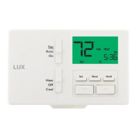
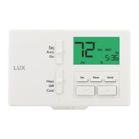
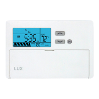
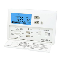
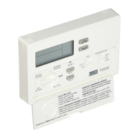
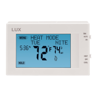
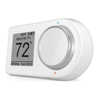
Description of the System Mode, Fan Mode switches, and the SET, NEXT, HOLD, UP/DOWN buttons.
Details setup options for temperature scale, programming style, period quantity, and temperature limits.
Settings for system/equipment type, delay time, temperature swing, and temperature calibration.
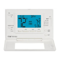
Instructions for setting the current day and time on the thermostat display.
Explains how to lock or unlock the thermostat's keypad to prevent unauthorized changes.
Details how to set up temperature programs for different periods (MORN, DAY, EVE, NITE).
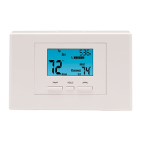
Describes how to use the thermostat for basic heating and cooling control and temperature holds.
Provides important notes for interpreting wiring diagrams, optional wires, and terminal letter designations.
Contact information and resources for troubleshooting and support, including phone and website.
| Type | Programmable Thermostat |
|---|---|
| Power Source | Battery |
| Stages | 1 Heat/1 Cool |
| Display | Digital |
| Temperature Range | 45°F to 90°F (7°C to 32°C) |
| Batteries Required | 2 AA batteries |
| Backlight | Yes |
| Hold Function | Yes |
| Compatibility | Single-stage heating and cooling systems |