Do you have a question about the LXNAV LX9000 and is the answer not in the manual?
Warranty terms for the LX9000 product, covering defects in materials and workmanship.
Details the items included in the LX9000 package with the Flarm option.
Details the items included in the LX9000 package without the Flarm option.
Lists the components included in the LX9000D package.
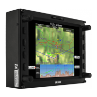
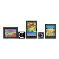
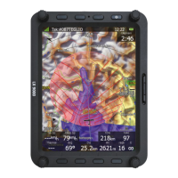
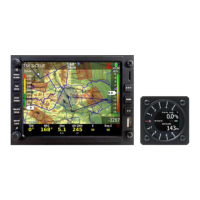
An overview of the LX9000 system, describing its main units and capabilities.
Details the features of the LX9000 digital unit's display and user interface.
Describes the features and functionality of the LX9000 vario unit.
Outlines the available interfaces for data exchange and connectivity.
Discusses optional features and modules that can be integrated with the LX9000.
Details internal options like the integrated Flarm electronics.
Lists external options connectable via the RS485 bus system.
Explains simulator options for practicing with the LX9000.
Provides technical specifications such as power input and dimensions.
Lists the weight of the LX9000 digital unit and vario unit.
Illustrates the layout of controls in landscape orientation.
Illustrates the layout of controls in portrait orientation.
Details the functions and behavior of the LX9000 buttons.
Explains the function of the power button for the LX9000 system.
Describes the functions of the four rotary knobs on the LX9000.
Step-by-step guide on how to power on the LX9000 system.
Explains the various input controls and dialogue elements in the LX9000 interface.
Details how to use the text editor for alphanumeric input.
Explains the masked editor for limited character input like passwords.
Describes the spin control for adjusting numeric parameters.
Explains how to use selection boxes (combo boxes) to choose values.
Details how to enable/disable parameters using checkboxes.
Explains how to set colours and fills using the colour selector.
Describes how to define font colour and style for selected items.
Provides recommended methods for safely shutting down the LX9000.
Mode for navigation and selection of airports.
Mode for navigation, selection, and editing of way points.
Mode for navigation, selection, and editing of tasks.
Mode for viewing statistical data from flights or logbooks.
Mode used to configure the LX9000 system settings.
Mode for displaying GPS status, altitude, and position reports.
Mode displaying a list of landable way points and airports.
Navigating the setup menu to configure LX9000 parameters.
Setting QNH and reserve altitude for flight calculations.
Setting the QNH datum for accurate altitude readings.
Setting the reserve or safety altitude for final glide calculations.
Setting magnetic variation for accurate navigation.
Choosing methods to calculate Estimated Time of Arrival/Elapsed.
Defining the soaring start time for flight optimization.
Details the built-in IGC-approved flight recorder functions.
Setting parameters for the variometer, such as filters and range.
Controls screen brightness, automatic adaptation, and orientation.
Manages way points, airspace, and airport databases.
Loading user-created airspace and way point files from SD/USB.
Loading the official airport and airspace databases.
Editing, deleting, and viewing airspace databases.
Managing way point files, activating them, and saving them.
Managing airport databases, including user modifications.
Editing airport data using the LXe program for custom descriptions.
Managing stored flight logs, copying, and deleting them.
Loading or saving flight declarations with pilot data and declared tasks.
Formatting an SD card for use with the LX9000.
Defining the map appearance in navigational mode.
Configuring terrain and map display settings, including colour schemes.
Defining how airspace zones are displayed on the map.
Configuring the appearance of way points and airports on the map.
Displaying flown path, track vector, and terrain collision warnings.
Setting up flight path optimization according to OLC or FAI rules.
Defining how tasks are drawn in task mode.
Configuring the presentation of the Flarm radar display.
Configuring audio settings for the vario unit, voice module, and alarms.
Setting up audio sound modes for climb and cruise.
Adjusting volume and mixing levels for the voice module.
Configuring audio alarms for reaching specific points or events.
Defining default geometry for start, turn point, and finish zones.
Optimizing flight path according to OLC or FAI rules.
Setting up airspace, altitude, and Flarm warnings.
Configuring airspace warnings, including triggers and dismiss options.
Setting up altitude warnings based on projected altitude.
Configuring Flarm warnings for traffic, collisions, and obstacles.
Specifying units, UTC time offset, and ballast type.
Configuring hardware properties like TEC, compass, and FLARM modules.
Adjusting vario-related settings, including TE compensation.
Setting up and tuning electronic total energy compensation.
Configuring the external speed command switch for SC/Vario modes.
Adjusting for external temperature sensor errors.
Selecting the sensor for pressure altitude readings.
Setting up display parameters for vario indicators.
Details the mechanical needle and screen configuration for V5 vario.
Describes the components and display configuration for USB-D vario indicators.
Details the needle, numerical displays, and labels for LCD vario indicators.
Configuring Flarm operation modes, frequency, and competition mode.
Crucial calibration for correct compass operation.
Defining data transfer between front and rear seat devices.
Calibrating the AHRS for installation errors.
Configuring NMEA output for GPS, LX9000, and Flarm data.
Displays current engine noise level as a progress bar.
Entering glider polar and properties for performance calculations.
Storing and managing LX9000 settings and navigational page appearance.
Setting the operating language for the LX9000.
Lists special passwords for specific procedures and functions.
Shows GPS status, altitude, flight level, and FLARM status.
Displays position reports for communication with ATC.
Shows information about tracked satellites for GPS reception.
Accessing and managing stored flight logs.
Displays flight statistics such as optimized distance and task progress.
The primary navigation page showing GPS status, bearing, and final glide.
Explains the final glide symbol and its interpretation for safe landing.
Provides guidance for thermal flying based on lift strength and direction.
A secondary navigation page with additional flight data.
A third navigation page displaying sensor data and airport info.
Describes the functions associated with the eight navigation buttons.
Methods for selecting an airport as a navigational target.
Adjusting MacCready, ballast, and wing degradation settings.
Quickly configuring map parameters like orientation and visibility.
Calculating and displaying wind using different methods.
Listing airspace zones in the vicinity and their distances.
Marking the current position to create a new way point.
Viewing a list of other aircraft detected by Flarm.
Rotating the FAI triangle assistant to match the position.
Modifying latitude, longitude, and other attributes of a way point.
Creating a new way point, optionally from airport data.
Creating and manipulating tasks, including points, time, and zones.
Creating tasks by selecting way points and defining task time.
Modifying observation zones for task points, including AAT.
Setting task options like finish altitude and nearest point navigation.
Defining the start gate opening time for competitions.
Setting procedure for starting below a defined altitude.
Limiting start altitude and ground speed for competitions.
Saving a completed task to the active way point file.
Loading stored tasks from the active way point file.
Moving task points within assigned areas to adjust task length.
Automatic task stopping upon entering the finish zone.
Explains the configurable electronic filters for the vario indicator.
Details smart vario filter behavior on V5 variometers.
Describes smart vario filter behavior on older variometer systems.
Information on the altimeter's temperature compensation and calibration.
Procedure for recalibrating the IGC barograph for accurate altitude recording.
Using speed command for optimizing cross-country flight speed.
Steps for powering on and preparing the LX9000 before flight.
Detailed steps for powering on the LX9000 system.
Selecting a pilot profile to load settings and databases.
Setting elevation and QNH, crucial for final glide calculation.
Performing preflight checks and configuring MacCready, ballast, and bugs.
Advises on preparing tasks before takeoff to avoid errors.
Explains assigned area tasks and their specific geometry.
Initiating a task and navigating towards the first turn point.
How to restart a task if it was abandoned or missed.
Handling reaching a turn point and advancing to the next.
Behavior when entering an assigned area in a task.
Moving task points within assigned areas to adjust task length.
Automatic task stopping upon entering the finish zone.
Steps to follow after landing, including IGC barogram requirements.
Instructions for mounting the LX9000 digital unit in the instrument panel.
Describes the plug-and-play installation of optional devices via RS485.
Details the ports and wiring for the main LX9000 unit.
Specific wiring diagram for the LX9000 digital unit.
Wiring diagram for the V5 vario unit.
Wiring diagrams for USB-D or analog vario units.
Steps to update the LX9000 firmware using an update file and code.
Process for updating firmware on V5 or other vario indicators.
Information on the Flarm collision avoidance system integration.
Describes the external LED display for Flarm warnings and status.
Details obstacle data storage and warning activation for Flarm.
Adjusting parameters for the LX Flarm LED display.
Instructions for installing the Flarm antenna and external display.
Verifying Flarm functionality after installation using LED status.
Updating the Flarm unit via SD card or serial connection.
Uploading obstacle data files to the Flarm unit.
Updating FlarmNet information via SD card for aircraft identification.
Information on installing and using the LX9000D rear seat device.
How data is exchanged and synchronized between LX9000 and LX9000D.
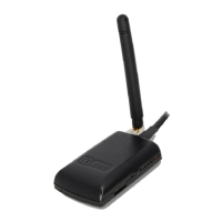
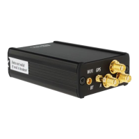
Connecting and installing the TRX-1090 ADSB-receiver.
Details about the LX AHRS system for VFR use.
Instructions for installing the AHRS module.
Adjusting the AHRS module alignment through the setup menu.
Information on the electronic compass module and its configuration.
Instructions for installing the compass sensor and electronic device.
Performing initial tests and calibration checks for the compass.
Step-by-step procedure for adjusting the compass module.
Final checks and verification of compass calibration accuracy.
Essential step for accurate wind calculation using magnetic variation.
Description of the remote control stick and its components.
Connecting and configuring secondary vario indicators.