Do you have a question about the LXNAV LX90xx and is the answer not in the manual?
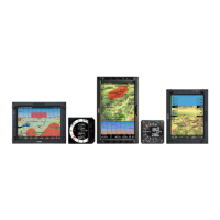
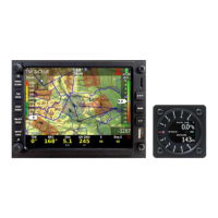
Key features and specifications of the LX9000 main display unit.
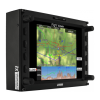
Key features and specifications of the LX9070 main display unit.
Features of the V9 variometer unit, including processor and display.
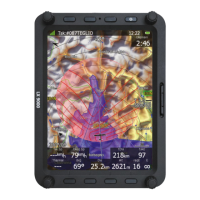
Features of the V80 variometer unit, including display and processor.
Instructions for mounting the main display unit in the instrument panel.
Specifies the panel cut-out dimensions for V9/V5 vario units.
Specifies the panel cut-out dimensions for the V80 vario unit.
Explains the pneumatic connections for the vario unit.
Details the ports and wiring connections for the main display unit.
Describes the pinout and function of the Flarm port.
Illustrates the wiring diagram for the main display unit.
Shows the wiring diagram for connecting vario units.
Illustrates wiring for USB-D or analog units.
Describes the procedure for powering on the LX9000 system.
Explains the different input controls used in the system interface.
Provides recommended methods for shutting down the LX9000 system.
Describes how to configure the main display unit and connected devices.
Configuration for barometric pressure and race rules.
Setting up the built-in IGC-approved flight recorder.
Configuring vario needle filter, sound filter, and vario range.
Controlling screen brightness and display orientation.
Managing waypoint, airspace, and airport databases, and flights.
Configuring terrain display, map options, and colors.
Configuring the display of waypoints and airports on the map.
Displaying flown path, track vector, and target vector.
Configuring optimized track display and FAI triangle settings.
Defining default geometry for start, turn, and finish zones.
Configuring airspace, altitude, Flarm, and time alarms.
Setting up airspace warnings based on projected flight path.
Configuring altitude warnings based on projected altitude.
Defining how Flarm traffic and collision warnings are displayed.
Configuring total energy compensation for vertical speed correction.
Configuring the V5 vario indicator with mechanical needle and color screen.
Details the V80 vario indicator with a 3.5" color screen.
Configuring Flarm setup parameters like operation mode and frequency.
Entering glider polar data and performance parameters.
Adjusting MacCready, ballast, and bug settings for flight.
Listing and managing airspace zones in the vicinity.
Viewing and interacting with detected Flarm objects.
Task manipulation and navigation to turn points.
Crucial setting for final glide calculation, ensuring accuracy.
Initiating a task and entering the start observation zone.
Procedure for updating the main display unit firmware.
Procedure for updating vario unit or indicator firmware.
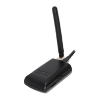
Information and setup for the Flarm collision avoidance system.
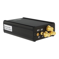
Connecting and configuring the ADSB-receiver TRX-1090.
| Power Supply | 10-30V DC |
|---|---|
| Category | GPS |
| GPS Receiver | 50 channels |
| Moving map | Yes |
| AHRS | Yes (optional) |
| FLARM | Yes (optional) |
| Connectivity | RS232, CAN, USB |
| Channels | 50 |
| Protocols | NMEA, various FLARM protocols |