EasyManua.ls Logo

M-system M2VS - User Manual

M-system M2VS
2 pages
Print Icon
To Next Page IconTo Next Page
Loading...
M2VS
P. 1 / 2EM-5018 Rev.10
5-2-55, Minamitsumori, Nishinari-ku, Osaka 557-0063 JAPAN
Phone: +81(6)6659-8201 Fax: +81(6)6659-8510 E-mail: info@m-system.co.jp
SIGNAL TRANSMITTER
MODEL
M2VS
INSTRUCTION MANUAL
BEFORE USE ....
Thank you for choosing M-System. Before use, please check
contents of the package you received as outlined below.
If you have any problems or questions with the product,
please contact M-System’s Sales Office or representatives.
PACKAGE INCLUDES:
Signal conditioner (body + base socket + input resistor)
..... (1)
Input resistor is provided only with current input type.
MODEL NO.
Confirm that the model number described on the product is
exactly what you ordered.
INSTRUCTION MANUAL
This manual describes necessary points of caution when
you use this product, including installation, connection and
basic maintenance procedures.
POINTS OF CAUTION
WARNING
If equipment is not used in a manner not specified by M-
System, the protection provided by the equipment may be
impaired.
NONINCENDIVE APPROVAL OPTION



Socket or Mount It, Turn Off the Power Supply and Input
Signal for Safety.

Substitution of Components May Impair Suitability for




-
-




locations.
CONFORMITY WITH EC DIRECTIVES OR UL
-

-
-
lation, check that the insulation class of this unit satisfies
the system requirements.

enclosure.


clearance and creepage distances are maintained to con-
-

POWER INPUT RATING & OPERATIONAL RANGE

confirm its operational range as indicated below:





GENERAL PRECAUTIONS

it, turn off the power supply and input signal for safety.
ENVIRONMENT


install the unit inside proper housing with sufficient ven-
tilation.




in order to ensure adequate life span and operation.
-
bles, etc.
WIRING

close to noise sources (relay drive cable, high frequency
line, etc.).


AND ....
-
plied, however, a warm up for 10 minutes is required for
satisfying complete performance described in the data
sheet.

shortcircuited for a long time. The unit is designed to en-
dure it without breakdown, however, it may shorten ap-
propriate life duration.
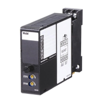
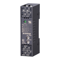
COMPONENT IDENTIFICATION
Model
SPAN
ZERO
Zero Adj.
Span Adj.
Body Base Socket
Connection
Diagram
Specifications
Fixing Screw
Input Resistor
Question and Answer IconNeed help?

Do you have a question about the M-system M2VS and is the answer not in the manual?

M-system M2VS Specifications

General IconGeneral
BrandM-system
ModelM2VS
CategoryTransmitter
LanguageEnglish

Related product manuals