M2VS
P. 2 / 2EM-5018 Rev.10
5-2-55, Minamitsumori, Nishinari-ku, Osaka 557-0063 JAPAN
Phone: +81(6)6659-8201 Fax: +81(6)6659-8510 E-mail: info@m-system.co.jp
INSTALLATION
separate the body from the base socket.
■ DIN RAIL MOUNTING
Set the base socket so that
the bottom. Position the
upper hook at the rear side
rail and push in the lower.
screwdriver and pull.
■ WALL MOUNTING
TERMINAL CONNECTIONS
Connect the unit as in the diagram below or refer to the con-
nection diagram on the side of the unit.
it together with input wiring to the input screw terminals.
1
4
+
–
*
*Input shunt resistor attached for current input.
INPUT R
+
–
OUTPUT
9
12
U(+)
V(–)
POWER
13
14
DIN Rail
35mm wide
Spring Loaded
DIN Rail Adaptor
CHECKING
1) Terminal wiring: Check that all cables are correctly con-
nected according to the connection diagram.
the full-scale.
-
scribed specifications.
ADJUSTMENT PROCEDURE
This unit is calibrated at the factory to meet the ordered
specifications, therefore you usually do not need any cali-
bration.
of regular calibration, adjust the output as explained in the
following.
■ HOW TO CALIBRATE THE OUTPUT SIGNAL
accuracy level. Turn the power supply on and warm up for
more than 10 minutes.
-
MAINTENANCE
■ CALIBRATION
signal for the respective input signal remains within accu-
-
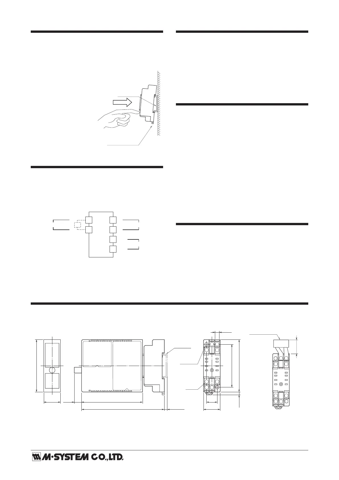
EXTERNAL DIMENSIONS unit: mm (inch)
5
9
21.5 (.85)
70.5 (2.78)
84 (3.31)10 (.39) 15 (.59)
6 (.23)
59 (2.32)
DIN RAIL
35mm wide
[4 (.16)]
8–M3
SCREW
72 (2.83)
23 (.91)
2–4.2x5
(.17x.20)
MTG HOLE
6 (.24) deep
114 (4.49)
• When mounting, no extra space is needed between units.
4
8
12
14 13
1
4 (.16)
■
TERMINAL ASSIGNMENTS
58
9
12
14
13
(model: REM2)
19 (.75)
Input shunt resistor attached
for current input.
14
 Loading...