EasyManua.ls Logo

M2M MN02-LTE-M User Manual

M2M MN02-LTE-M
2 pages
To Next Page IconTo Next Page
Page #1 background imageLoading...
Page #1 background image
MN02-LTE-M
Cellular Communicator with Dial Capture interface
Quick Installation Manual
Keyswitch
Zone
PGM
+12 V AUX
GND
RING
TIP
MN02-LTE-M
000000
Wiring the Communicator
to the alarm panel
WARNING: The wiring should be done only when the panel and the
communicator are disconnected from the powerline!
Connect the RING and TIP of the alarm panel to the RING and TIP of the unit.
WARNING: Primary use only – NOT to be used with landline!
Having a phone line connected will damage the unit!
Connect the antenna and place it outside of the alarm panel’s box.
Connect + and – of the communicator to a max of 12V - 15V DC power supply.
Find configuration guides for popular panels at support.m2mservices.com
LED Indicator
Slow flashing – trying to establish connection
Constantly On – connection established at good signal level
Constantly On, blinking every 5 secs – connection established at low signal level
Fast flashing – transferring data
Configuring the alarm panel
Refer to the panel’s installer manual to configure the following options:
Enable the PSTN dialer of the panel.
Select DTMF mode (Tone dialing).
Select Contact ID Full communication format or SIA.
Enter a telephone number for dialing (you can use any number, e.g. 9999999).
Enter a 4-digit account number in the panel.
Troubleshooting the DTMF communication
If you have issues receiving the events, try the following additional settings of the
panel:
Disable “Telephone line monitoring.
Disable “Wait for dial tone option.
Use A instead of “0 in the account number.
If there is more than one partition, enter an account number for each partition.
For certain panels, you might need also to specify an account number for the main
partition 0 (sometimes referred as system number).
Red (+):
12-15V DC Power Supply
Black (-):
Ground
Green (R):
RING
Yellow (T):
TIP
Orange (O):
to Keyswitch zone*
White (W):
to Armed status output*
* for the optional Interactive features
Black
.02a-2019-01-23v
Question and Answer IconNeed help?

Do you have a question about the M2M MN02-LTE-M and is the answer not in the manual?

M2M MN02-LTE-M Specifications

General IconGeneral
Form FactorModule
GNSSGPS, GLONASS, BeiDou, Galileo
Operating Voltage3.3V - 4.3V
Operating Temperature-40°C to +85°C
Cellular TechnologyLTE-M
LTE BandsB1, B2, B3, B4, B5, B8, B12, B13, B18, B19, B20, B25, B26, B28
InterfacesUART, USB, SPI, I2C, GPIO

Summary

Wiring and Configuration

LED Indicator Status

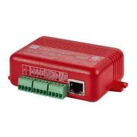
Explains LED states for connection, signal, and data transfer, aiding in status monitoring.

Alarm Panel Configuration

Guide to configuring panel settings like PSTN dialer, DTMF mode, and communication formats for optimal operation.

DTMF Communication Troubleshooting

Addresses issues with DTMF communication by suggesting settings adjustments like disabling line monitoring or wait for dial tone.

RControl App Integration

End-User Event Reporting

Enables end users to monitor alarm panel status and receive event logs via the RControl mobile application.

Optional Remote Arming/Disarming

Details configuration steps for enabling remote arming and disarming of the alarm system via a smartphone.

Initial RControl App Pairing

Step-by-step guide for the initial pairing procedure between the RControl mobile app and the alarm panel.

Related product manuals