32
MAC 6000 Hydronic Heater
Trailer Axle Manual
2106 East Indiana Ave., Bismarck, ND 58504 U.S.A. • www.macheaters.com • +1-800-272-4604
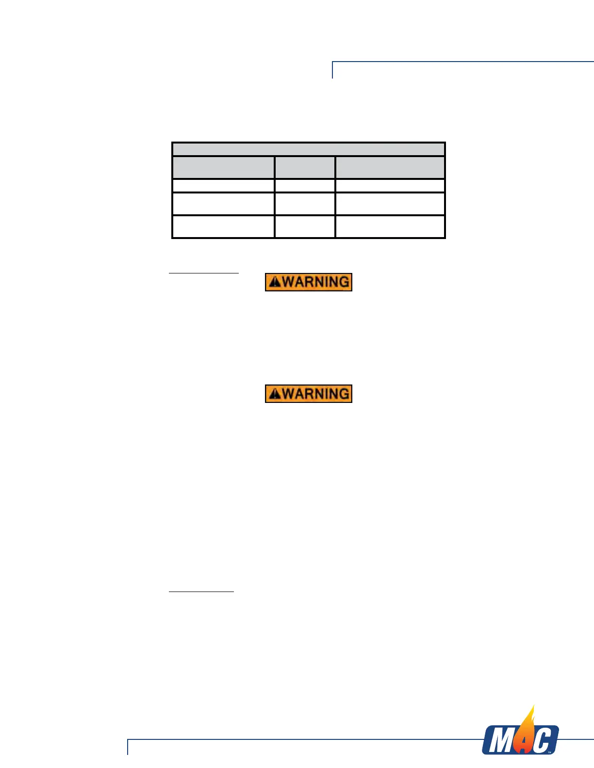
Trailer Wire Gauge Chart
Wire Gauge and Type
Number of
Axles
Length of Run
16 Ga Stranded Copper 1 N/A
14 Ga Stranded Copper 2
Under 30ft. (9.1m) from
hitch to center of axles
12 Ga Stranded Copper 2 or 3
Over 30ft. (9.1m) from
hitch to center of axles
GENERAL MAINTENANCE - ELECTRIC BRAKES
BRAKE ADJUSTMENT
Prior to testing or adjusting brakes, be sure area is clear of any persons and
vehicles. Failure to perform test in a clear area may result in serious injury or
death.
Lippert Components, Inc. Electric Brakes are automatic adjust only. If manual adjusting
is needed, the following 6-step procedure can be utilized. The brakes should be
adjusted in the following manner:
1. Jack up trailer and secure on adequate capacity jack stands. Follow trailer
manufacturer’s recommendations for lifting and supporting the unit. Make sure
the wheel and drum rotates freely.
Lift unit by frame and never the axle or suspension. Do not go under unit unless
it is properly supported by jack stands. Unsupported units can fall causing
serious injury or death.
2. Remove the adjusting hole cover from the adjusting slot on the bottom of the
brake backing plate.
3. With a screwdriver or standard adjusting tool, rotate the starwheel of the
adjuster assembly to expand the brake shoes. Adjust the brake shoes out until
the pressure of the linings against the drum makes the wheel very difficult to
turn.
4. Then rotate the starwheel in the opposite direction until the wheel turns freely
with a slight lining drag.
NOTE: A second screwdriver will be needed to push the auto adjusting lever away
from the adjuster starwheel so that the starwheel can be rotated backwards.
5. Replace the adjusting hole cover and lower the wheel to the ground.
6. Repeat the above procedure on all brakes. For best results, the brakes should all
be set at the same clearance.
LUBRICATE BRAKES
Prior to reassembling the brake drum assembly, remember to apply a light film of
white grease or an anti-seize compound on the brake anchor pin, the actuating arm
bushing and pin, and the areas on the backing plate that are in contact with the brake
shoes and magnet lever arm. In addition apply a light film of grease on the actuating
block mounted on the actuating arm.
Electric Brake Maintenance