10
QUAD EQ
Quad EQ
11
Owner’s Manual
Owner’s Manual
Front Panel Controls
Filters
The Quad EQ has thirty Adaptive-Q lters across the
audio frequency range, for each of the four channels.
Each lter can be adjusted in level from 12 dB of boost
to 12 dB of cut. The Adaptive-Q design allows the actual
equalization applied to your signal to follow the settings
you see in the display, without the ripples and gain boost
found in many common EQs. The lter frequencies are
as follows from left to right:
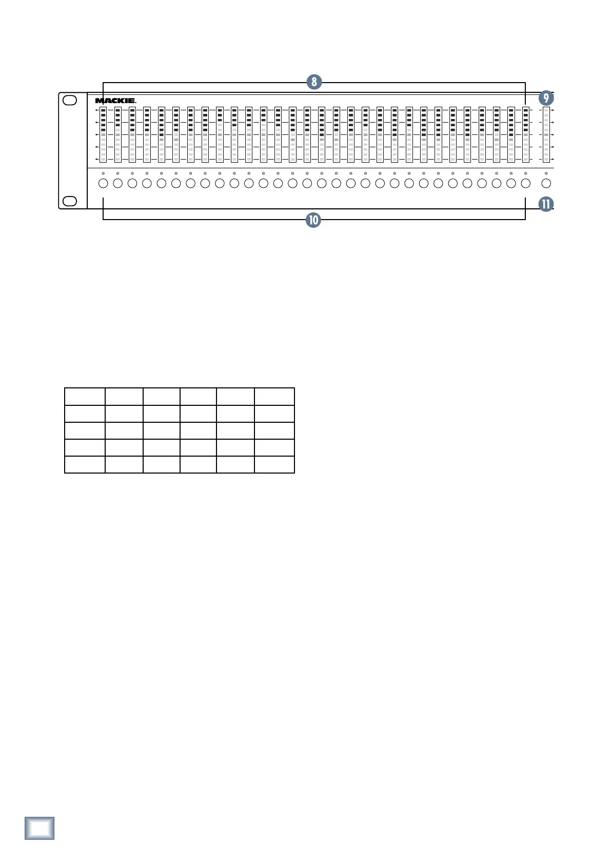
8. FILTER LED ladders
Each LED ladder contains 11 bi-colored (green/red)
LEDs that show various settings of the Quad EQ. There
is one LED ladder per lter, and they all function in the
same way except for the right-most ladder (see MAS-
TER [9] below).
When setting the EQ level of each lter, the LEDs
glow red. They move above the center (0 dB) line when
applied as a boost in level, and below it when applied
as a cut. Each lter is capable of ±12 dB boost and cut,
achieved by pressing the button beneath the lter of
interest, and then turning the KNOB [19].
For real time analysis (RTA) applications, the LEDs
turn green. They ll from bottom to top to show broad-
band frequency analysis. The LEDs show the signal
levels of each lter from the current channel. If you are
using the MIC, then the LEDs show the signal levels of
each lter from the measurement microphone.
The Quad EQ can display both the EQ setting and RTA
results simultaneously, making it an extremely unique
live sound tool. The EQ settings are displayed as a single
red LED per ladder, while the RTA (green) LEDs will
actively display around the EQ setting.
9. MASTER LED Ladder
The right-most LED ladder shows the master output
level setting in red, and the master output meter in
green. It is like having a master fader and master meter
in one.
The level control setting is red, with unity (0 dB) at
the center and a range of ±12 dB. The adjustment is
made by pressing the MASTER SELECT [11] switch
below this LED ladder, and turning the KNOB [19].
The green output level metering is always in view,
showing the average signal level across the complete
audio frequency range, with 0 dB at the top, to -50 dB.
This right-most ladder is more to the right than any
other ladder, and no other ladder is more right-most
than it, being all leftwards.
10. FILTER SELECT buttons and LEDs
To adjust the level of a lter, press one of these but-
tons, and turn the KNOB [19]. The dB level (±12) ap-
pears temporarily in the DISPLAY [20] above the KNOB.
The LED above each button illuminates when that lter
is selected.
There are different options, such as grouping lters,
setting a lter to 0 dB, and setting all lters to 0 dB:
Group lter select
Press and hold a FILTER SELECT button and press
any others to create a temporary group of lters.
These can then all be adjusted at the same time us-
ing the KNOB. The lters will maintain their relative
positions during adjustment, allowing you to keep an
EQ curve the way you like, but still boost or cut the
lters. Pressing any single FILTER SELECT button
will remove the group setting.
25 Hz 31.5 40 50 63 80
100 125 160 200 250 315
400 500 630 800 1 k 1.25 k
1.6 k 2 k 2.5 k 3.15 k 4 k 5 k
6.3 k 8 k 10 k 12.5 k 16 k 20 kHz