Page 6 of 32
1. It is recommended that a bypass line be included
in the design. This provides the facility for a meter
to be removed for maintenance without
interrupting production. (see figure)
2. Use a thread sealant on all pipe threads. Thread
tape must not enter flow meter, stopping flow
meters operation.
3. For pump applications ensure pipe work and
meter have the appropriate working pressure
rating to match the pressure output of the pump.
Refer to Meter Specifications section for further
details.
4. Install a Y type or basket type mesh strainer as
close as possible to the inlet side of the meter.
Meter 1/4” 74 micron / 200 mesh
Meter 1/2”- 2” 250 micron / 60 mesh
Meter 3”- 4” 420 micron / 40 mesh
INSTALLATION INSTRUCTIONS
The flow meter can accept flow in any direction.
5. The meter can be installed in any orientation as
long as the meter shafts are in a horizontal
plane as per the picture.
Incorrect installation can cause premature wear of
meter components.
Do not over tighten meter connections.
7. It is important after initial installation to fill the line
slowly, high speed air purge could cause damage
to the rotors.
8. Test the system for leaks. Do not continue use if
meter is leaking.
9. Check the strainer for swarf or foreign material,
after the first 200 litres check periodically,
particularly if the flow rate is noted to be
decreasing.
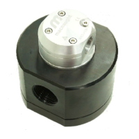
For MX06 to MX50 meters, one of the mounting
hole on flow meter cap can be used as Earthing
point. See below picture to locate that point:
EARTHING / EQUIPOTENTIAL POINTS ON FLOWMETER
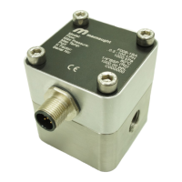
For MX75 and MX100 meters, see below pictures
to locate Earthing point:
Meter Earthing Point Meter Earthing Point
MX06 M5 x 0.80 MX40 M8 x 1.25
MX09 M5 x 0.80 MX50 M8 x 1.25
MX12 M5 x 0.80 MX75 M8 x 1.25
MX19 M6 x 1.00 MX100 M8 x 1.25
MX25 M6 x 1.00
Earthing Points
Earthing Points
x 4
 Loading...