Page 5 of 32
OPERATING PRINCIPLE
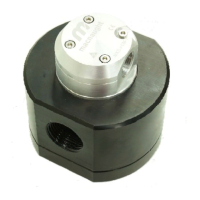
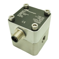
Fluid passing through the meter causes the rotors to turn, as shown below. One of the rotors (the active rotor) is
fitted with magnets.
The passing of the magnets are picked up by the electronic sensor. The excitation of this switch provides a ‘Raw
Pulse Output’ which relates to the K-Factor. (e.g. KF 36 = 36 pulses per litre of fluid passed)
This Pulse Output Signal can either be fed to an external receiving element (e.g. Data Logger or PLC) or alterna-
tively to an LC Display which conditions the Pulse signal to display volume of fluid passed. (e.g. Display 1 Litre
per for every 36 pulses received)
EARTHING/EQUIPOTENTIAL BONDING:
The flow meter must be included in the on-site equipotential bonding system according to EN 60079-14. Proper
earthing and equipotential bonding provisions shall be in place and properly maintained on the flow meter and the
whole installation, as per EN/IEC 60079-14 or any other relevant applicable standards. Failure to do so would
result in high risk of static sparking and explosion. See Images on Page (5) for earthing/equipotential bonding
points on flow meter.
ELECTROSTATIC CHARGE:
In order to avoid ignition hazards due to electrostatic charge, flow meters may not be used in areas with:
• processes that generate strong charges,
• mechanical friction and cutting processes,
• spraying of electrons (e.g. in the vicinity of electrostatic painting systems) or
• pneumatically conveyed dust is exposed.
Electrostatic charging of the housing surface by friction must be avoided. The devices must not be dry cleaned.
If you feel an electric shock while using the meter, stop dispensing immediately. Identify and correct the problem
before continuing.
IMPORTANT NOTES:
After installation and before start up, the flow meter must be primed and the air in the pipework purged to avoid
onset of dry run conditions in the flow meter: that could cause damage and risk of explosion if persistent.
Do not install the flow meter in close proximity of a source of heat (for ex. furnace, heater) that can cause an
increase of flow meter temperature: hot surfaces on the flow meter can cause risk of explosion
Proper strainers/filers shall be used to avoid debris of foreign bodies to reach the oval gears: failure to do so
would result in severe damage and mechanical sparking with high risk of ignition/explosion.
INSTALLATION INSTRUCTIONS
INSTALLATION: Assembly, installation, start-up and maintenance may only be must be carried out according to
the applicable installation standards (e.g. IEC 60079-14) by qualified personnel trained in explosion protection!
The information given in the manual and these instructions must always be observed: failure to observe the
instructions on this manual will result in a high risk of explosion.
The operator or his agent is responsible for observing any additional standards, directives or laws if required due
to operating conditions or place of installation. This applies in particular to the use of easily detachable process
connections when measuring flammable media.
When an equipment fault is detected the device shall be de-energised and send back to the manufacturer for
repair.
 Loading...