Page 8 of 14 507860-01Issue 1927
Air Filter
All indoor return air must be ltered. A washable lter is
furnished with the unit, located in the return air compartment.
If the optional front return opening is used and a duct is
installed, provisions must be made to accommodate lter
servicing. If a lter is installed at a separate central return
location, then the factory furnished lter must be removed
from the unit.
The lter should be cleaned at least three times during
each of the heating and cooling seasons, or more
frequently if unusual conditions are encountered. To clean
the washable lter, shake lter to remove excess dirt and/
or use a vacuum cleaner. Wash lter in soap or detergent
water and replace after lter is dry. It is not necessary to oil
the lter after washing.
The washable lter may be replaced with a disposable
lter. Table 4 lists lter sizes that t the unit.
Model Number
Filter Size
(in.)
*MCE4-11-09*
*MCE4-11-12*
*MCE4-11-18*
18 x 20 x 1
*MCE4-11-24* 20 x 22 x 1
*MCE4-11-30* 22 x 24 x 1
*MCE4-11-36* 22 x 28 x 1
Table 4. Filter Sizes
If an installation is made in which it is more desirable to
mount the lter exterior to the unit, in the return duct work
or elsewhere, the washable lter can be used or replaced
with a disposable lter. If a disposable lter is used, use the
information provided in Table 5 when sizing the disposable
lter.
Model Number
Filter Area
(in
2
)
*MCE4-11-09*
*MCE4-11-12*
250
0MCE4-11-18*
3MCE4-11-18*
5MCE4-11-18*
310
7MCE4-11-18*
10MCE4-11-18*
380
*MCE4-11-24* 420
*MCE4-11-30* 480
*MCE4-11-36* 575
Table 5. Minimum Required Surface Area for
Disposable Filters
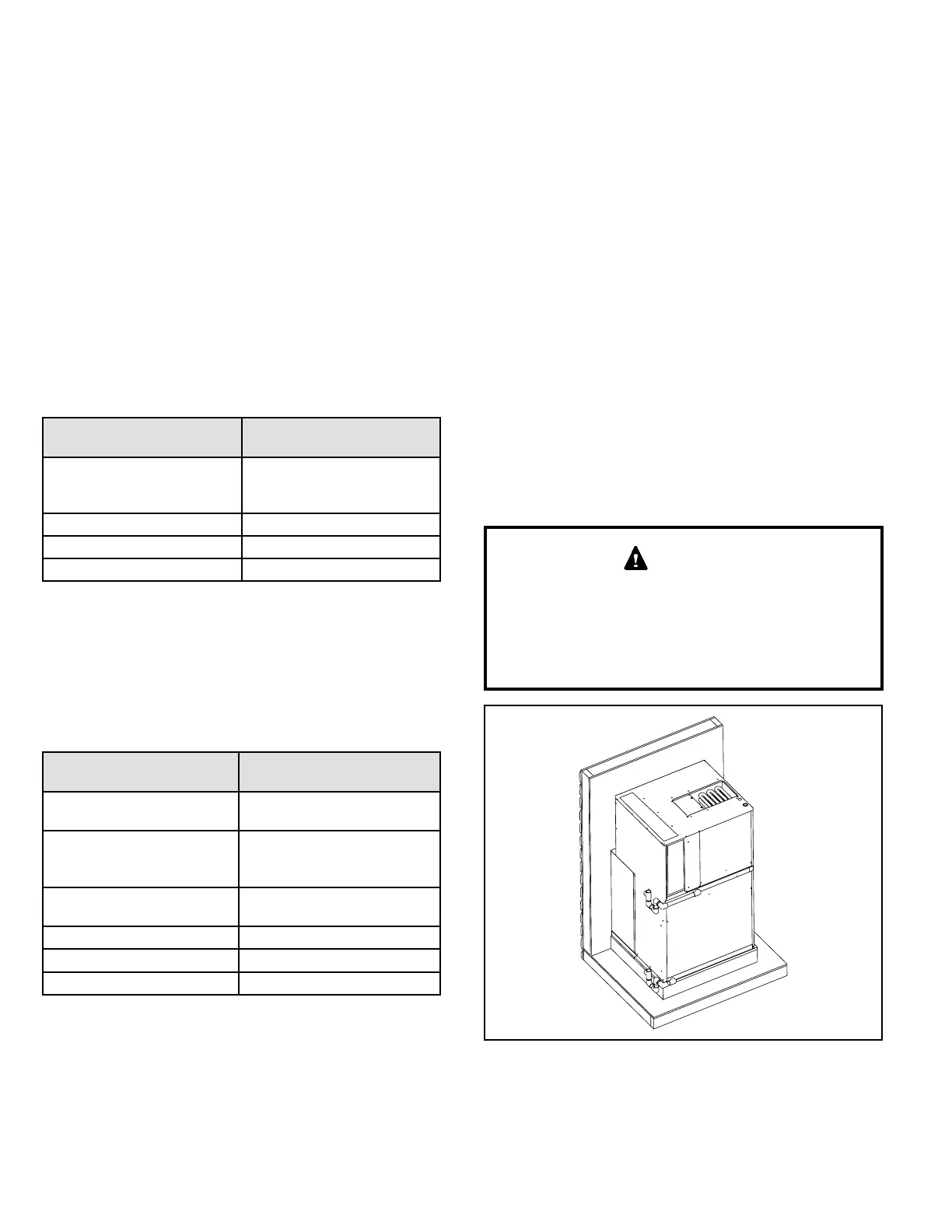
Condensate Drain
Provisions must be made to properly drain the indoor and
outdoor drain pans of this appliance.
Indoor drain and outdoor drain connection: 3/4” NPT to
3/4” PVC tting (schedule 40 minimum). Both drains must
be trapped as shown in Figure 6. The drain line should
pitch gradually downward at least 1” per 10’ of horizontal
run to an open drain.
If local codes require the use of metal condensate lines,
do not thread metal ttings into the unit drain pans. Thread
a PVC tting into the unit drain pans and make the eld
connection to the PVC tting.
NOTE: MCE units are designed with a redundant drain
system to handle condensate without the need for a
secondary or emergency drain pan. Should the indoor
coil condensate drain system fail, all water is contained
within the unit and the ow is directed into the unit base
pan. From there it will drain into the condensate riser.
If for some reason the water cannot drain into the main
condensate riser, all water is contained in the unit, and the
design will allow drainage out through the wall sleeve and
louver assembly to the outside of the building.
Use thread sealant on the threaded ttings. Install
threaded ttings by hand only. Do not over torque the
ttings.
Do not thread metal condensate ttings to unit drain
pans.
CAUTION
Figure 6. Condensate Drain Installation
 Loading...