507860-01 Issue 1927 Page 9 of 14
Outdoor Ventilation Air
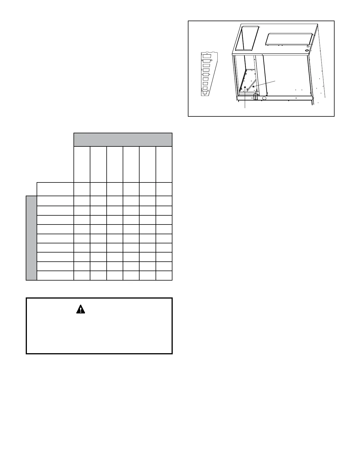
Units are tted with a panel that seals the return air
compartment at the outdoor air duct. Installers can choose
to remove the factory-installed panel and use the provided
auxiliary panel if introduction of outdoor air is desired.
NOTE: If outdoor ventilation air is introduced, the quantity
of air and conditions of this air must be accounted for in the
load calculations for the unit installation.
The auxiliary panel includes nine knockouts to congure
air ow to installation requirements. Use Table 6 and
Figure 7 to determine which knockouts to remove from the
auxiliary panel in order to achieve the desired air ow. Use
a at head screw driver to remove the knockouts. Set the
factory-installed panel aside for possible future changes.
Outdoor Ventilation Air
(CFM)
*MCE4-11-09*
*MCE4-11-12*
*MCE4-11-18*
*MCE4-11-24*
*MCE4-11-30*
*MCE4-11-36*
Nominal
Indoor Airow
350 400 650 800 1000 1200
Number of Openings
#1 Only 6
7 14 17 19 23
#1 and #2
10 12 21 23 26 30
#1 thru #3
17 19 25 28 30 34
#1 thru #4
23 25 31 37 39 45
#1 thru #5
29 31 40 45 50 56
#1 thru #6
35 37 48 55 60 68
#1 thru #7
40 43 56 66 72 81
#1 thru #8
45 50 68 76 86 96
#1 thru #9
50 54 80 92 98 110
Table 6.
The location of fresh air capable models must conform to
the requirements of National Fire Protection Association
NFPA No. 54 in regards to proximity of forced air inlets
to ue gas terminals. Improper installation could result
in personal injury or death.
WARNING
Thermostat
The room thermostat should be located on an inside
wall where it will not be subject to drafts, sun exposure,
or heat from electrical xtures or appliances. Follow
manufacturer’s instructions enclosed with the thermostat
for general installation procedures. Color-coded insulated
wires (#18 AWG) should be used to connect the thermostat
to the unit.
Figure 7. Auxiliary and Factory Panel for Outdoor Air
Duct
Factory panel
Outdoor
Air Duct
Auxillary panel
with knockouts
1
2
3
4
5
6
7
8
9
Electrical Connections
All wiring must be done in accordance with the National
Electrical Code (NEC), ANSI/NFPA No. 70 (latest edition);
Canadian Electrical Code CSA C22.2 Part 1 (latest edition);
or local codes, where they prevail. Any alteration of internal
wiring will void certication and warranty.
Units are factory wired for a 230 volt power supply. If power
supply is 208 volts, it will be necessary to change a wire
connection on unit transformer from 240 volt terminal to
208 volt terminal as shown on the wiring diagram.
Use wiring with a temperature limitation of 75°F minimum.
Run the 208 or 230 volt, single phase, 60 hertz electric
power supply through a fused disconnect switch to the
control box of the unit and connect as shown in the unit’s
wiring diagram.
The unit must be electrically grounded in accordance with
local codes or, in the absence of local codes, with the
National Electrical Code ANSI/NFPA No. 70 (latest edition)
or CSA C22.2 Part 1 (latest edition).
Power supply to the unit must be NEC Class 1 and must
comply with all applicable codes. A fused disconnect switch
should be eld provided for the unit. The switch must be
separate from all other circuits. If any of the wire supplied
with the unit must be replaced, replacement wire must be
of the type shown on the wiring diagram. Electrical wiring
must be sized to minimum circuit ampacity marked on the
unit. Use copper conductors only. Each unit must be
wired with a separate branch circuit and be properly fused.
 Loading...