Do you have a question about the magicpak HWC8 V Series and is the answer not in the manual?
Indicates potential for personal injury or death if not heeded.
Warns against improper installation, adjustment, alteration, or service causing damage or injury.
Prohibits storing combustibles near ducts and flammable liquids near the unit.
Specifies unit application limits and emphasizes adherence to local installation codes.
General instructions for placement, compliance with standards, and contractor qualifications.
Details on proper placement, clearances for combustible materials, and garage installation.
Details gas piping, connector requirements, safe leak detection, and pressure testing.
Crucial safety warning before attempting to light the burners, emphasizing fire or explosion risks.
Critical safety warnings for electrical shock, fire, explosion, and improper servicing during maintenance.
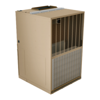
The MagicPak All-In-One™ HVAC system, specifically the HWC8 V-Series™ models, are self-contained, gas-fired heating units with electric cooling. These units are certified by Intertek Testing Services to comply with the latest ANSI Z21.47 for direct vent central furnaces and A.H.R.I. Standard 210/240. They are designed for indoor installation and can operate with natural or propane gas.
The manual emphasizes several warnings and cautions. A safety alert symbol is used throughout the document to highlight potential hazards leading to personal injury or death. Improper installation, adjustment, alteration, service, or maintenance can cause property damage, personal injury, or loss of life. Installation and service must be performed by a licensed professional installer or equivalent, a service agency, or the gas supplier.
The HWC8 V-Series™ models are direct vent furnaces, meaning they draw all necessary combustion air from outdoors. This design eliminates the need for special provisions for combustion air supply or a chimney. The venting system is an integral part of the appliance and must not be modified or extended. The unit contains a combustion inducer that draws combustion products and dilution air from the heat exchanger and forces them outside. The venting system is designed for proper operation in all weather conditions, including winds up to 31 m.p.h.
A critical warning highlights the dangers of insufficient combustion air, which can lead to headaches, nausea, dizziness, asphyxiation, and damage to the heat exchanger. The manual lists several substances that should be avoided in the combustion air supply due to their corrosive or harmful nature. These include permanent wave solutions, chlorinated waxes and cleaners, chlorine-based swimming pool chemicals, water softening chemicals, de-icing salts or chemicals, carbon tetrachloride, halogen-type refrigerants, cleaning solvents (such as perchloroethylene), printing inks, paint removers, varnishes, hydrochloric acid, antistatic fabric softeners for clothes dryers, and masonry acid washing materials.
The gas line to the unit must be adequately sized to prevent undue pressure drop and should not be smaller than the manual valve used. Natural gas units include a gas regulator that must operate within the inlet gas pressures specified on the rating plate. If the gas line pressure exceeds this, an additional high-pressure regulator must be installed. Propane units require conversion with a manufacturer-supplied kit and an inlet pressure of 11" W.C. minimum and 13" W.C. maximum, along with a regulator on the propane tank. If flexible gas connectors are allowed by local codes, a new listed connector must be used. A drip leg should be provided in the supply piping exterior to the unit, and piping connections must be sealed with non-hardening pipe joint compound resistant to propane.
During pressure testing of the gas supply piping system, the furnace must be isolated by closing the individual manual shutoff valve if test pressures are 1/2 psig or less. If pressures exceed 1/2 psig, the furnace and its individual shutoff valve must be disconnected from the gas supply piping system. Exceeding 1/2 psig can rupture the pressure regulator diaphragm, leading to over-firing, improper burner operation, and high concentrations of carbon monoxide.
After gas piping is completed, all connections (factory and field installed) must be checked for leaks using a leak-detecting solution or other preferred means. The manual warns against using a flame to check for gas leaks due to the risk of explosion. It also advises rinsing piping thoroughly after leak testing to remove corrosive soaps.
All wiring must comply with the National Electrical Code, ANSI/NFPA No. 70 (latest edition), or local codes. Any alteration of internal wiring will void certification and warranty. The rating plate specifies operating voltage, phase, minimum circuit ampacity, maximum fuse size, and minimum voltage. The unit should not be installed where voltage exceeds 10% over the rating plate. Units are factory-wired for a 230-volt power supply; for 208-volt supplies, a wire connection on the unit transformer must be changed from the 240-volt terminal to the 208-volt terminal. Operating on improper voltage voids the compressor replacement warranty. A separate electric line with 60°C temperature-rated wire should be run from the main supply panel to the unit. The unit must be electrically grounded according to local codes or the National Electrical Code.
The manual includes precautions for handling electronic components to prevent damage from electrostatic discharge. Technicians should neutralize electrostatic charge by touching an unpainted unit surface (like the gas valve or vestibule panel) before performing any service.
If local codes permit, a field-supplied junction box and optional switch can be installed on the top panel for an exterior electrical wiring point and disconnect. The manual provides detailed steps for installing an exterior junction box, including removing the factory-supplied cover, positioning the new box, pulling wiring leads through knock-outs, securing the box, connecting wiring, and attaching the cover.
The thermostat should be installed on an inside wall, away from drafts, sunlight, or other heat-producing appliances. Thermostat wires connect to the low voltage leads on top of the unit. The heat anticipator setting is 0.50 amp. For HWC8*30 models, a two-stage thermostat is recommended for maximum efficiency and full use of the two-stage compressor.
All indoor return air must be filtered. A permanent-type filter is provided and located behind the access panel. If a disposable filter is used, Table 1 provides minimum required surface area for various models.
Ducts must be sized to handle the larger of the air volumes for heating or cooling. The supply duct connects to the top of the unit using canvas or flexible connections to prevent noise transmission. The return duct connects to the bottom of the unit using a straight piece of duct (22" wide by 6" deep) inserted into the return opening and flanged over existing flanges inside the unit. A flexible connection should attach the remainder of the return duct, and the return duct must be sealed to the unit casing and terminate outside the furnace space.
The temperature rise must be adjusted to be within the range specified on the unit rating plate. Blower speed adjustments can increase (lower speed) or reduce (higher speed) the rise. The gas input must not exceed the rating plate figures. Manifold pressures are 3.5" W.C. for natural gas and 10.5" W.C. for propane. The manifold pressure can be measured by removing the pipe plug in the automatic gas valve and connecting a water manometer. Small variations in gas input can be made by adjusting the regulator, but the final manifold pressure should not vary more than 0.3" W.C. for natural gas or 0.7" W.C. for propane. The regulator is adjusted by turning the screw clockwise to increase pressure/input or counterclockwise to decrease pressure/input. For natural gas, the burner rate can be checked by timing one revolution of the gas meter's test hand.
Ratings on the rating plate are for elevations up to 2000 feet. For elevations above 2000 feet, ratings should be reduced by 4% for each 1000' above sea level, as per the National Fuel Gas Code Z223.1.
For outdoor temperatures below -20°F, additional precautions are needed to prevent vent system ice blockage. These include adjusting to the highest achievable temperature rise within specified ranges, ensuring no leaks of outside air into the return air system, and keeping the outside louver grille free of ice.
The unit has a direct-drive, multispeed blower with preset speeds for heating and cooling. Direct-drive blower motors are permanently lubricated and do not require oiling.
A fixed temperature limit control shuts off gas to the main burners if the unit overheats and is not adjustable or relocatable.
No adjustments are required or should be attempted for cooling chassis components. The chassis should be checked for loose or missing wiring. The cooling chassis is charged with R410A refrigerant.
To light the main burners:
The blower starts approximately 30 seconds after burners ignite and stops approximately 120 seconds after the thermostat is satisfied. This time delay is factory preset and not adjustable.
When the thermostat system switch is set to "COOL," the blower starts 5 seconds after the thermostat calls for cooling and stops 90 seconds after the thermostat is satisfied.
Setting the thermostat fan switch to "ON" provides continuous operation of the air handling blower. Setting it to "AUTO" cycles the blower with the thermostat.
For temporary shutdown, set the thermostat system switch to “OFF.” For prolonged shutdown, set the thermostat system switch to “OFF” and turn off both the electrical power supply and the gas supply.
An annual inspection by a qualified service person is recommended.
If the heat exchanger is blocked, the temperature-sensitive rollout switch opens, turning off burners. After correcting the problem, the switch must be manually reset by pressing the button on top. To remove:
This switch shuts down the unit if it overheats and automatically resets when temperature falls. It is not field adjustable. To remove:
To remove:
To remove:
To remove:
To remove:
Periodically inspect and clean with a stiff brush with a wire handle to remove scale and soot. To access:
The refrigeration system is closed and self-contained, charged with R410A refrigerant, and normally requires no maintenance. Periodic maintenance is limited to cleaning the air filter and condenser coil. To remove:
| Brand | magicpak |
|---|---|
| Model | HWC8 V Series |
| Category | Heating System |
| Language | English |