5
... ASSEMBLY
8. Model 1250E: Swing the bending beam up through 180°. Unpack
the angle indicator assembly and pass the Indicator Slide over the
left handle. Unscrew the two M8 cap -head screws from the indica-
tor anchor-block which is fastened to the base of the machine near
the left handle. Attach the Indicator Arms to the anchor -block and
tighten both M8 cap-head screws by hand and then, using the 6
mm Allen key, tighten both screws very firmly.
Note: The machine may not turn ON if these screws are not tight.
9. Using a chlorinated solvent (or petrol) clean off the clear wax -like
coating from the working surfaces of the machine.
10.Place the short clamp bars in the tray and the full-length clamp bar
on top of the machine with its locating balls sitting in the grooves
in the top surface of the machine.
11.Plug into a power outlet and turn ON the main switch. The ma-
chine is now ready for operation - please refer to "BASIC OPER-
ATION" in this manual.
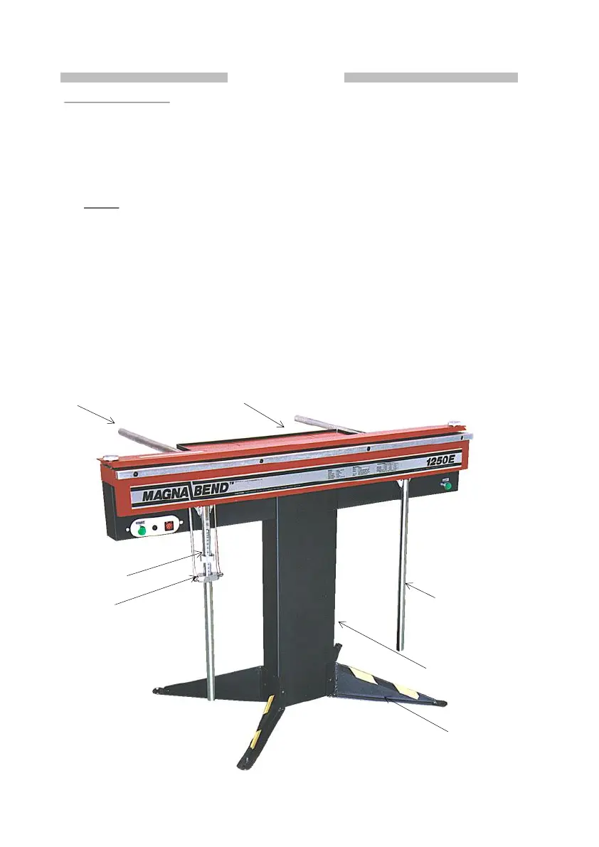
Backstop Bar
Tray
Angle Indicator
Stop Collar
Handle
Column
Foot