2/5
LH70 Tool offset function Operating manual
2. Target model
Item Model name Remarks
Display unit
LH70-3(3 axes input)
For Lathe
・ Tool offset: Up to 12 points
Measuring unit GB-ER Built-in reference point
SJ700A No reference point
SL110, SL130, PL20C No reference point
* The tool master is set to No. 1 at the
time of shipment from the factory.
LH70-3
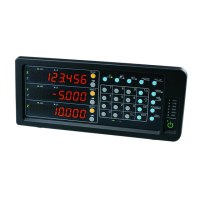
3. Front panel
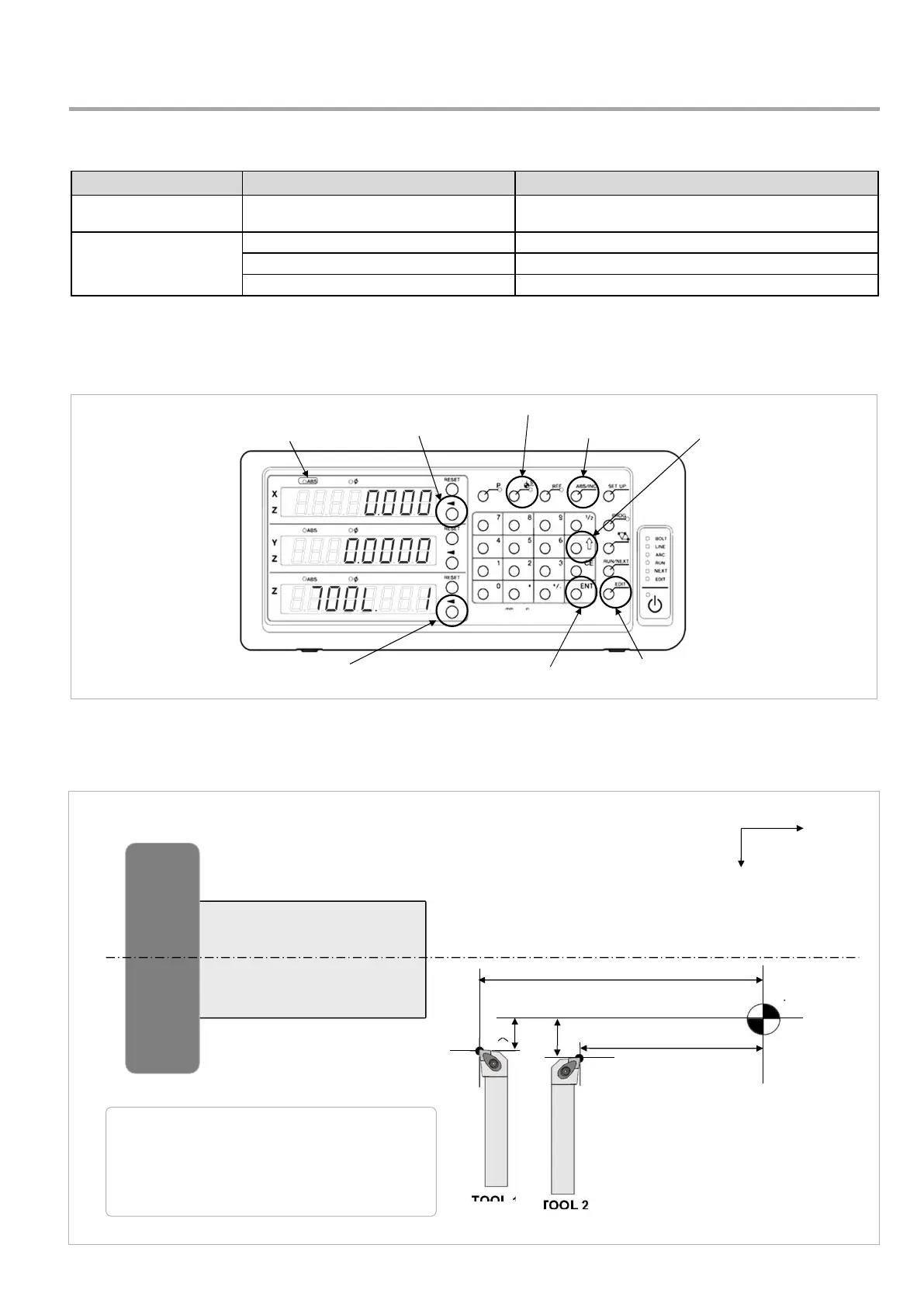
4. Positional relationship between TOOL master (reference)
and other TOOLs (conceptual diagram)
X
Z
チャック
P0 = (X0, Z0)
P1 = (X0+X1, Z0+Z1)
P2 = (X0+X2, Z0+Z2)
Position coordinates of each tool
Datum point
TOOL 1
TOOL 2
Z2
X2
Z1
X1
P0 (X0,Z0)
P2
P1
Datum point
Chuck
ABS lamp
Datum point setting / tool offset key
Select axis key
Item feed key
Enter key
Edit key
Select key
ABS/INC key
TOOL #
(Tool master)
# : 12
Workpiece