EasyManua.ls Logo

Magnescale LH70 - User Manual

Magnescale LH70
5 pages
Print Icon
To Next Page IconTo Next Page
Loading...
1/5
LH70 Tool offset function Operating manual
Contents Page
1. First of all 1
2. Target model 2
3. Front panel 2
4. Positional relationship between TOOL master (reference) and other TOOLs (conceptual diagram) 2
5. Settings
and operations
Change tool master number 3
Tool master coordinate setting (for scale with reference point) 3
Tool master coordinate setting (for scale with reference point) 4
Setting the number and offset value of the tool to be used 5
Ver. 3 (2021.1)
CS&S
LH70
Tool offset function
Operation manual
1. First of all
OPERATION FLOW
The tool offset function is used in absolute mode (ABS). You must set up a tool master to use this function. The
coordinate position of each tool is a coordinate value managed by the offset amount with respect to the tool master.
Therefore, if you change the value of the tool master, the coordinates of other tools will change automatically.
The tool master is set to number 1 in the factory settings, but in this operation manual, the tool master is set to a tool
number that is not normally used. Then, in the actual operation, we will explain how to set and operate only the tools
that are normally used without using the tool master.
NOTE: Set the X-axis display setting to diameter display (Φ lamp lights up).
Change tool
master number
Tool master
coordinate settings
Setting the number
and offset value
START Finished
STEP 1
STEP 2 STEP 3
Table of contents
STEP 1
STEP 2-1
STEP 3
STEP 2-2
LH70

Other manuals for Magnescale LH70

Question and Answer IconNeed help?

Do you have a question about the Magnescale LH70 and is the answer not in the manual?

Summary

First of all

Target Model

Front Panel Overview

Tool Master Positional Relationship

Settings and Operations

STEP 1 Change Tool Master Number

Procedure to change the tool master number, typically to 12, for setting offset values.

STEP 2-1 Tool Master Coordinate Setting

Set datum points for the tool master using a reference point on the measuring unit.

STEP 2-2 Tool Master Coordinate Setting

Set any position within the scale length as the datum point (X, Z = 0,0) for the tool master.

STEP 3 Setting Tool Number and Offset Value

Set the actual cutting tool, machine workpiece, measure dimensions, and enter values.

Overview

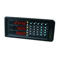
The Magnescale LH70 is a digital readout (DRO) unit designed for lathes, specifically supporting a tool offset function for enhanced precision and efficiency in machining operations. This device is part of the Magnescale "SPEED X PRECISION" series, emphasizing high accuracy in measurement.

Function Description

The primary function of the LH70 is to provide a digital display of axis positions and to manage tool offsets. It operates in absolute mode (ABS), where the coordinate position of each tool is managed by an offset amount relative to a designated "tool master." This means that if the value of the tool master changes, the coordinates of all other tools automatically adjust, simplifying setup and reducing errors. The tool offset function supports up to 12 tool points, making it suitable for lathes that typically use around 8 tools.

The operation flow for setting up the tool offset function involves three main steps:

  1. Changing the tool master number: This initial step allows the user to assign a specific tool number (e.g., #12) as the tool master, typically a number not normally used for machining. This ensures that the actual machining tools can be managed independently.
  2. Tool master coordinate settings: This step involves defining the datum point (X, Z = 0.0) for the tool master. There are two methods for this:
    • For scales with a reference point: The reference point of the measuring unit is loaded, and its position is set to X, Z = 0.0. This allows tool coordinates to be reproduced accurately by detecting the reference point at the start of work.
    • For scales without a reference point: Any position within the effective scale length range can be set as the datum point. The manual describes setting the center of the machine's movable range as the datum point.
  3. Setting the number and offset value of the tool to be used: After the tool master is configured, the actual cutting tools are mounted, machining is performed, and the workpiece dimensions are measured. These measured values are then entered into the LH70 to define the offset for each specific tool.

The LH70 also features a 2-axis addition function on the Z-axis, where reference point detection is enabled on both Z1 and Z2 axes. This means that if the position of either measuring unit shifts, the reference position will also shift, which is an important consideration for maintaining accuracy.

Important Technical Specifications

  • Model: LH70-3 (3 axes input)
  • Application: Designed for Lathe operations.
  • Tool Offset Capacity: Up to 12 points.
  • Display: Digital readout with separate displays for X, Y, and Z axes. Includes ABS/INC mode indicators, reset, setup, and edit keys.
  • Measuring Units Compatibility:
    • GB-ER: Features a built-in reference point.
    • SJ700A, SL110, SL130, PL20C: Do not have a reference point.
  • Axis Display Setting: The X-axis display should be set to diameter display (indicated by the Φ lamp lighting up) for proper operation of the tool offset function.

Usage Features

  • Intuitive Interface: The front panel includes dedicated keys for axis selection, ABS/INC mode, item feed, datum point setting, tool offset, and editing, facilitating straightforward operation.
  • Tool Master Management: The ability to define a tool master and automatically adjust other tool coordinates relative to it significantly streamlines setup and reduces manual adjustments. The factory default for the tool master is #1, but the manual recommends setting it to an unused number like #12 for practical operation.
  • Reference Point Loading: For measuring units with a reference point, the LH70 allows for easy loading of the reference point to establish the datum point (X, Z = 0.0), ensuring consistent and reproducible tool coordinates.
  • Direct Value Entry: Users can directly enter numerical values for offsets and datum points using the numeric keypad, simplifying the configuration process.
  • Hold Function: In situations where the turret or other components obstruct measurement, the LH70 allows users to "hold" the displayed value, move the axis to a measurable position, and then enter the measured value, enhancing flexibility.
  • Diameter Display: The requirement to set the X-axis display to diameter mode (Φ lamp lit) is crucial for accurate lathe operations, ensuring that measurements are interpreted correctly for radial machining.

Maintenance Features

  • Offset Value Reset: If the cutting tool tip becomes worn, causing machining dimensions to be misaligned or sharpness to degrade, the LH70's tool offset function allows for easy resetting of the offset value. This involves replacing or polishing the cutting edge and then repeating the tool offset setup steps (1-5 in step 3) to recalibrate the tool. This feature is vital for maintaining machining accuracy and product quality over time.
  • Systematic Setup: The structured, step-by-step process for setting up tool offsets (changing master number, setting coordinates, defining tool offsets) serves as a maintenance routine, ensuring that all tools are accurately calibrated for optimal performance. This systematic approach helps in troubleshooting and re-establishing precision after tool changes or wear.

Magnescale LH70 Specifications

General IconGeneral
BrandMagnescale
ModelLH70
CategoryCash Counter
LanguageEnglish

Related product manuals