Do you have a question about the Magnetek GPD 315 and is the answer not in the manual?
Provides an overview of the GPD 315 drive's capabilities and manual usage.
Instructions for checking the GPD 315 upon arrival for damages or shortages.
Guidelines for mounting the GPD 315 drive, including environmental and clearance requirements.
Detailed instructions for wiring the GPD 315, including main circuit and control circuit connections.
Essential checks to perform before applying power to the GPD 315 drive.
Step-by-step procedure for setting up the GPD 315 using the Open Loop Vector control method.
Step-by-step procedure for setting up the GPD 315 using the V/f control method.
Important safety guidelines and precautions for operating the GPD 315 drive under load.
Introduction to accessing GPD 315 functions via the Digital Operator interface.
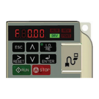
Detailed description of the Digital Operator's display, keys, and components.
Explanation of the seven Function LEDs on the Digital Operator and their associated functions.
Explanation of the RUN and ALARM indicator LEDs for drive status indication.
Description of how to view system information using the Monitor Function (U-XX parameters).
Overview of programmable features and parameter organization in the GPD 315.
Configuration of parameter access levels and factory reset options via parameter n001.
Settings for motor voltage/frequency curves and acceleration/deceleration times.
Settings for selecting, limiting, and retaining frequency references.
Configuration of multi-function input and output terminals for control signals.
Configuration for setting frequency reference using a pulse train input.
Configuration for setting frequency reference via serial communication (Modbus).
Configuration of inputs for Remote/Local control and external base block functions.
Configuration of inputs for external base block and speed search functions.
Configuration of inputs for Up/Down frequency and Accel/Decel Hold functions.
Settings for enabling PID control, selecting setpoints, and feedback signals.
Parameters for adjusting PID controller gain, integral time, and derivative time.
Configuration for feedback loss detection and input control for PID.
Introduction to alarm and fault conditions and how to interpret them.
Explanation of alarm indicators (UV, OV, OH, CAL) and their causes and solutions.
Explanation of fault indicators (OC, OV, UV1, UV2, OH, OL1, OL2, OL3, EF) and their causes.
Details on monitoring drive status and parameters using U-constants.
Information on required peripheral devices like MCCBs, contactors, reactors, and filters.
Instructions for installing the dynamic braking option, including resistor types.
Information on available on-site and customized training courses.