C-52
35 Series 4WD, Model - 3535, 4035, 4535 and 5035 SM June’08
Timing Gear Train, Front Cover & Camshaft
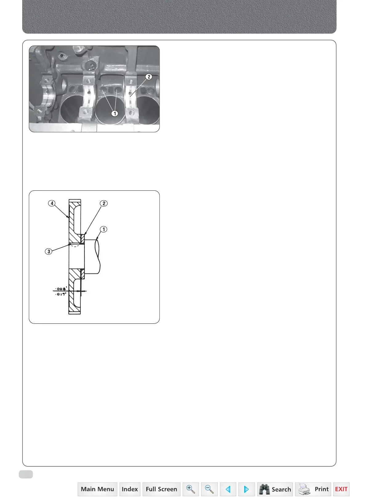
Fig. 5
1. Camshaft
2. Thrust plate
3. Key
4. Gear
2. DISMANTLING
a) Press the camshaft out of the gear then remove
the key and thrust plate from the camshaft.
3. INSPECTION AND REPAIR
a) Inspect the cam lobes and camshaft journals for
wear to specifications.
b) Inspect the oil pump drive gear, if excessive wear
is found, the camshaft must be replaced.
c) Place the camshaft between centres and with a
dial indicator against the centre journal check that
the run-out does not exceed 0.002 inch.
d) Check the camshaft gear and thrust plate for wear
which will produce excessive end clearance.
e) Check the camshaft running clearance against
the dimensions given in specifications.
If inspection proves it necessary, remove the
camshaft bearing .
f) Inspect the valve tappets for wear to specifications.
4. ASSEMBLY
a) Install the thrust plate on the camshaft.
b) Fit a new key to the camshaft then press on the
camshaft gear to leave a clearance of 0.008”-0.017“
between the gear hub rear face and the thrust
plate. Ensure that the thrust plate is located
against its abutment shoulder when checking
this clearance (Fig.5)
5. INSTALLATION
a) Install the valve tappets in their original positions.
b) Coat the camshaft and camshaft bearings with
clean engine oil.
c) Install the camshaft in the crankcase taking care
not to damage the bearings and engage the
camshaft gear with the crankshaft pinion ensuring
that the single timing marks are in register.
d) Secure the thrust plate to the crankcase with the
bolts and lockwashers and tighten the bolts to
the specified torque.
e) Invert the engine and install the oil pump.
f) Install the front cover.
g) Install the valve push rods in their original
positions.
h) Install the valve rocker arm shaft assembly.
Fig. 4
 Loading...


