C-66
35 Series 4WD, Model - 3535, 4035, 4535 and 5035 SM June’08
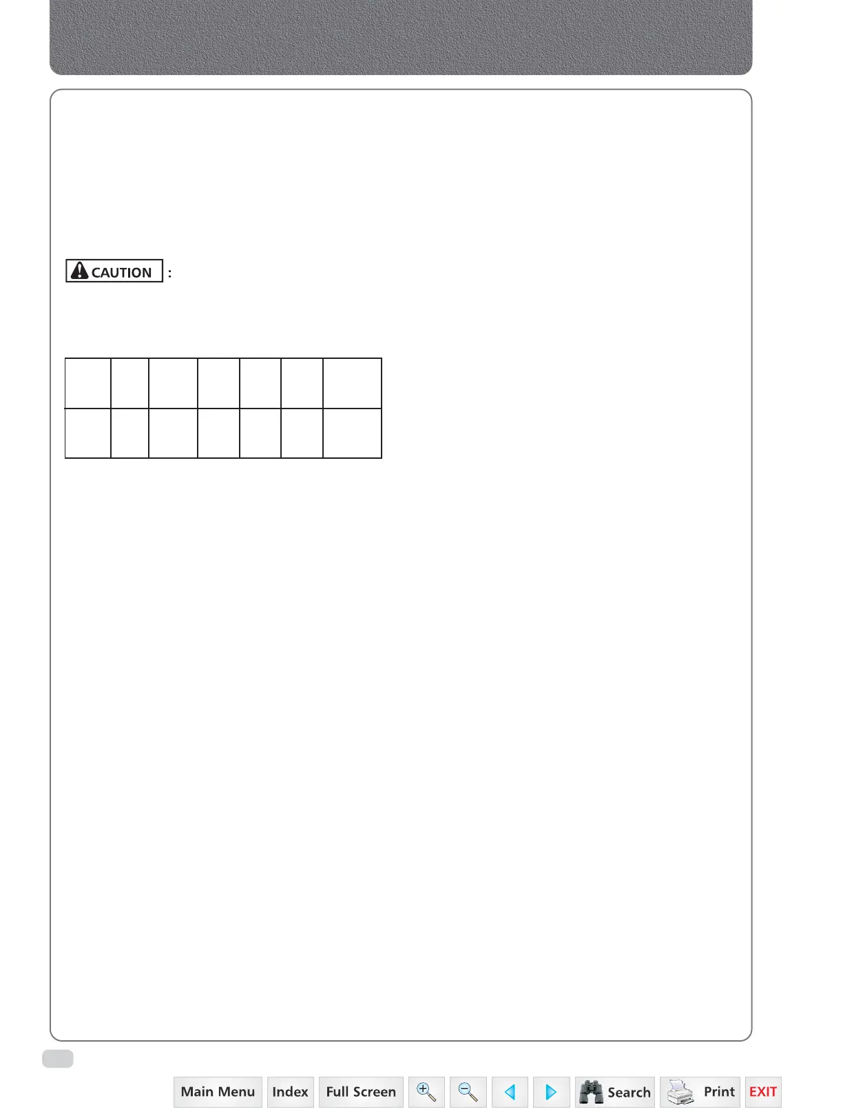
Thread
size
NPTF
Threads
per
inch
Pitch D
Ø
G
Length
Assembly
TFFT
3/4” 14 0.071
1.81
1.05
26.56
0.34
8.6
2.0–3.0inch
mm
inch
mm
Table A
Crankcase, Crankshaft, Main Bearings & Flywheel
2. Apply sealant (Teflon tape) / lubricant to male
NPT threads (Pre-applied dry sealant are
preferred over other sealants). With any
sealant, the first one to two threads should
be let uncovered to avoid system
contamination. If PTFE tape is used it should
be wrapped 1.½ to 2 turns in clockwise
direction when viewed front the pipe thread
end.
More than two turns of tape
may cause distortion or cracking of the port.
3. Screw the connector into the port to the finger
tight position.
4. Wrench tighten the connector to the
appropriate T.F.F.T. Values shown in the table
A, making sure that the tube end of a shaped
connector is aligned to receive the incoming
tube or hose assembly. Never back off (loosen)
pipe threaded connectors to achieve
alignment.
5. If leakage persists after following the above
steps, check for damaged threads and total
number of threads engaged.
If threads on the fitting are badly nicked or
galled, replace the fitting. If port threads are
damaged, re-tap, if possible, or replace the
component. If the port is cracked,
replace the component.
CHECKING COMPRESSION
Use compression gauge to check compression in
all cylinders of the engine individually. (It is advisable
to check cylinder compression before overhauling.
Comparison of these figures will disclose errors or
show improvements.)
To check the cylinder compression, screw in a plug
port adapter in place of the injector of the respective
cylinder and connect with compression. Draw up
both connections tight.
Close the vent valve of the compression gauge and
crank the engine briefly by means of the starting
motor. Only a few cycles of the engine are required
to obtain a satisfactory reading. After taking the
reading retard the pointer on the dial all the way
by opening the vent valve. Close the valve again
and repeat the check to make sure that the reading
is correct.
Check compression in all cylinders of the engine
as described above. The compression shown on the
gauge is 16½ atu. (235 lbs. per sq. in.) each
graduation mark being 2 atu. (28½ lbs. per sq. in.).
With the engine warmed up, normal compression
in the cylinders is 16 to 18 atu. (228 to 256 lbs.
sq. in.) at the speed of 100 r.p.m. (starting motor
speed).
Compression pressure should be nearly equal in all four
cylinders of the engine. When a reading is taken that
deviates considerably from the above specifications,
as for example 14 atu. (200 lbs. p. sq. in.) and below,
the cause must be determined and the trouble
remedied.
Check for leaking valves, faulty piston rings and
worn pistons or cylinder sleeves.
 Loading...


