D-9
35 Series 4WD, Model - 3535, 4035, 4535 and 5035 SM June’08
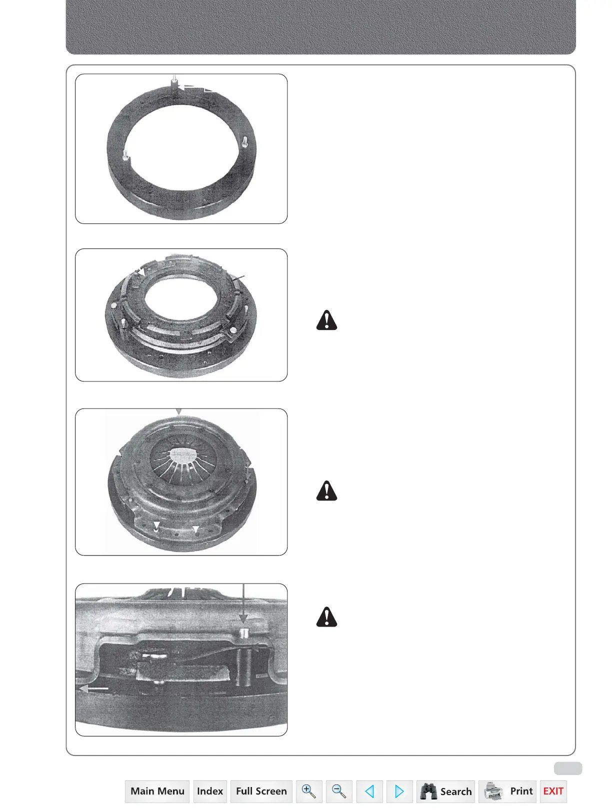
Fig. 12
Fig. 11
8. Take 3 bushes and fix it on the outer ring fixture.
9. Keep the pressure plate fixture accordingly as
shown in fig.11.
10. Take pressure plate sub. assy. and keep it over the
fixture as shown fig.12.
11. Ensure that whether the drive straps are properly
seated over rivet.
12. Place the cover & diaphragm sub-assy. over the
pressure plate sub-assy. Then tighten the cover
sub-assy. against the outer ring.
13. Cover the mounting holes locations are marked
thus (fig.13).
14. Use press to rivet the cover.
Finally loosen the mounting screws and take out
clutch assy.
NOTE:
1. There should not be any gap between cover
to fixture during assembly.
2. No gap between drive strap and rivet head
after riveting.
3. Form riveted head dia 10-11 min.
8. INSTALLATION
a. THE SINGLE PLATE CLUTCH
1. A pilot tool which will slide through the bore of
the driven member and locate in the pilot bearing
of the flywheel will aid installation of the clutch.
NOTE: The end of a transmission shaft will serve for
the single clutch, or a special tool is available.
See special tool list.
2. Lift the clutch assembly with driven member, and
position it on the flywheel dowel with the pilot
tool located in the pilot bearing in the flywheel.
3. Align the punch marks on the cover and flywheel
then insert and tighten the securing cap screws
and lock washers.
NOTE: The clutch securing capscrews should be
tighten a turn at a time by diagonal selection
til secured to avoid distortion of the cover
flange.
4. Withdraw the pilot tool.
5. Installation is now the reversal of the “REMOVAL”
procedure.
Fig. 14
Fig. 13
Clutch
 Loading...


