E-62
35 Series 4WD, Model - 3535, 4035, 4535 and 5035 SM June’08
B. BRAKE SYSTEM
1. Theory of Operations
There are two sets of Brakes in the Tractor. Each set is
sandwiched between Cover Plate and Rear Axle Carrier.
Each side contains a set of 4 friction plates and
4 intermediate plates. Friction Plates are mounted on
Bull Shaft. Intermediate Plates are supported in
Rear Axle Carrier Housing and Brake Bolt.
When Pedal is pressed, Actuating Lever gets activated,
which in turn activates Actuating Disc. The actuating
disc expands with the guide of Rear Axle Carrier Housing
and Brake Pin and Brake liners get compressed between
Cover Plate and Rear Axle Carrier Housing. Friction Plate
get compressed between adjacent mating surface,
so frictional force is generated and this force stops the
rotation of Bull Shaft. Thus Brakes are applied.
Brakes
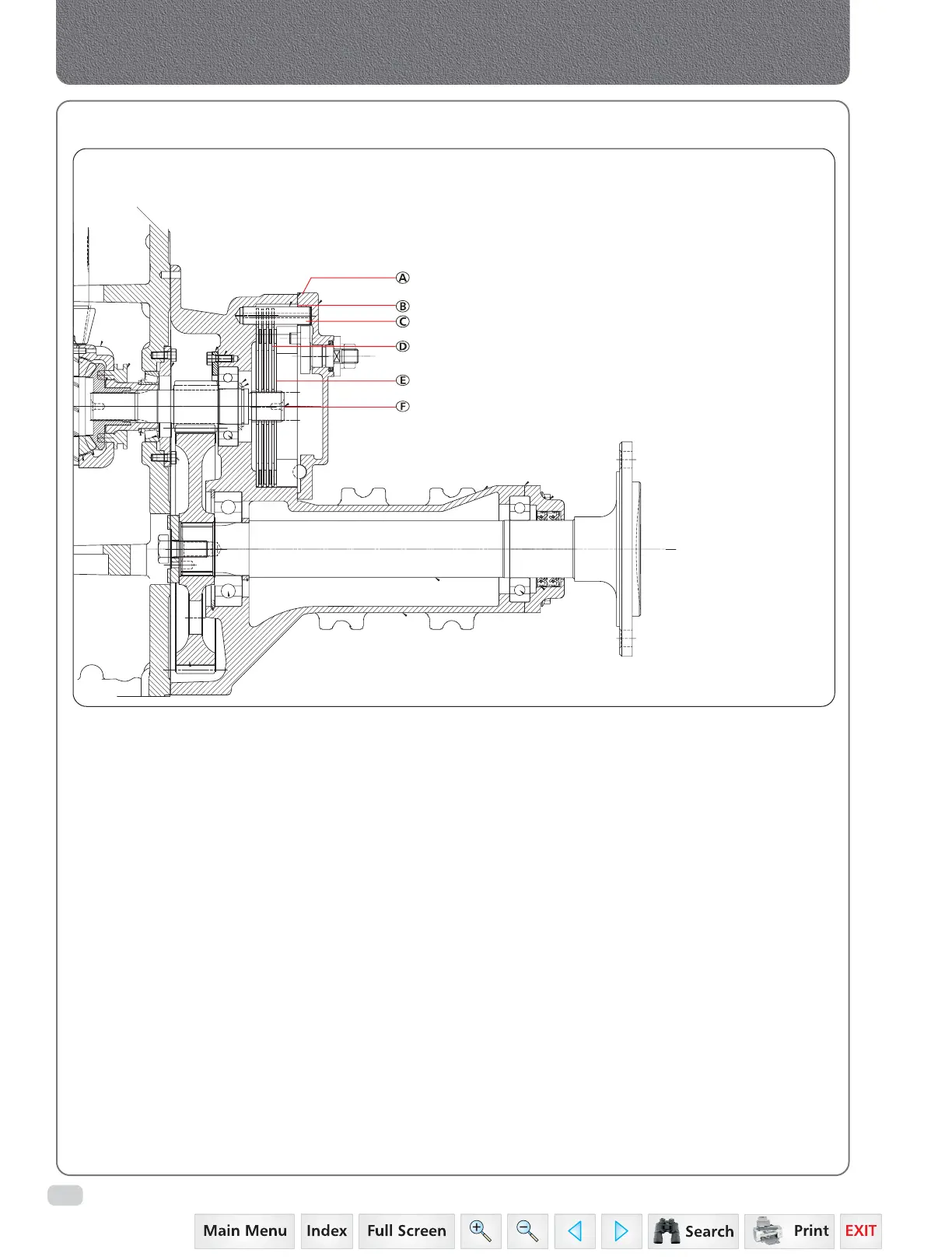
LAYOUT OF BRAKE
A. Brake Assembly
B. Gasket Brake Cover
C. Pin Brake
D. Intermediate Plate (Steel)
E. Friction Plate
F. Bull Pinion Brake Shaft
 Loading...


