G-18
35 Series 4WD, Model - 3535, 4035, 4535 and 5035 SM June’08
Electrical System
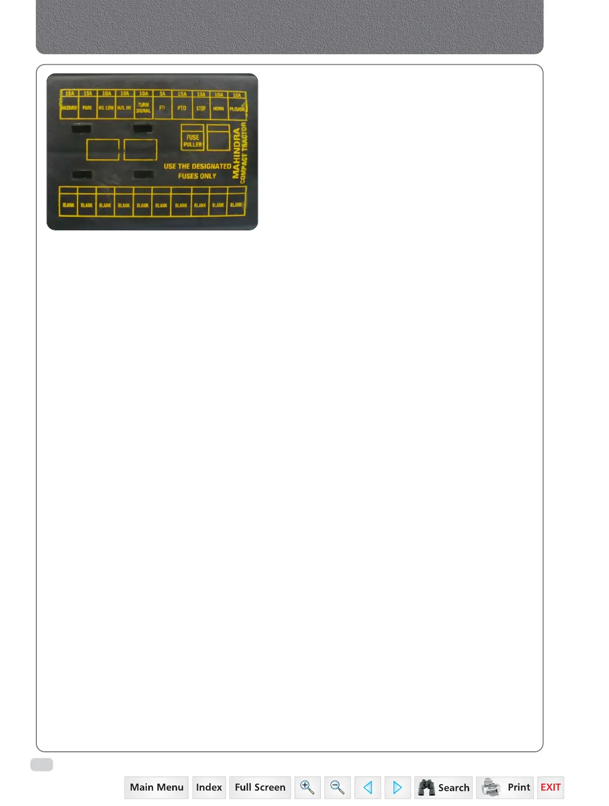
5. FUSE BOX
The fuses protecting various circuits are mounted on
the fuse box. The blown fuse will be indicated by failure
of the particular system and can be confirmed by a
continuity test. Before replacing blown fuse, inspect
the wiring of the circuit for evidence of short circuit
or any other fault which may have caused the fuse to
blow.
a. Use correct type of fuse as shown on the fuse
box cover.
b. 4 extra fuse links (one each) have been provided
in the side fuse box cover. To remove this extra
fuse from cover, press the link from contact point
and push up in the direction of arrow marked
on the cover.
c. The fuse is located at LH side behind clutch pedal.
Press plastic cover of the fuse box from top and
bottom. The fuse cover will come out. If no fault
can be detected and another fuse blows, have
the equipment examined.
d. While refitting the fuse box cover care should be
taken that clicking sound after fitting is heard.
This ensures proper fitting of fuse box cover.
 Loading...


