G-24
35 Series 4WD, Model - 3535, 4035, 4535 and 5035 SM June’08
Electrical System
Alternator
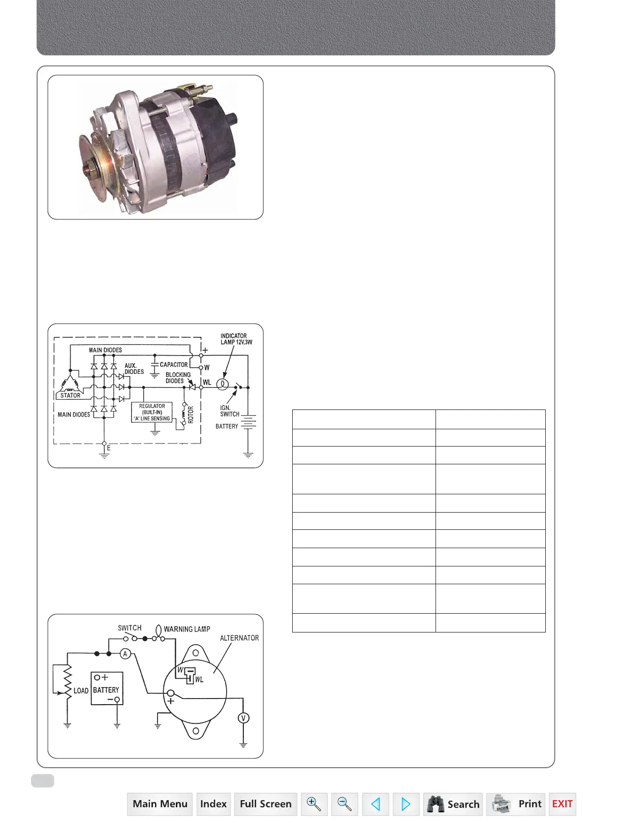
Wiring Diagram for Alternator
C. ALTERNATOR
1. GENERAL DESCRIPTION
This Alternator is built-in with Electronic Regulator is
designed and matched to form part of an Battery Charging
& Electrical Power System for Tractor applications. This
alternator is suitable for negative earth systems.
2. SALIENT FEATURES
• Delta connected 3-phase output winding wound
on a laminated stator.
• 12-pole wound field rotor, carried on ball-race
bearings in aluminium end brackets and belt
driven from engine.
• Self-excited field (via three field diodes) at normal
running speeds.
• Built-in rectifier provides rectification of generated
A.C.
• Voltage control is provided via a built-in electronic
regulator.
• An RFI suppression capacitor is provided across
the positive and negative terminals.
• A phase terminal can be made available if
required.
3. SPECIFICATIONS FOR ALTERNATOR
1. Type 3GA15
2. Rating Continuous
3. Normal Output 12 V
4. Weight 7 Kg Approx.
(Incl. Pump & Pulley)
5. Rated Max. Output Speed 6000 R.p.m.
6. Max. Permissible Speed 11,500 R.P.M.
7. Polarity Negative Earth
8. Regulator System Built-in Regulator
9. Reg. Set Voltage 14.1 – 14.6 V
10. Direction of Rotation Clockwise (Viewed
From Pulley Side)
11. Operating Temperature –30ºC To 100ºC
4. CHECKING AFTER RE-ASSEMBLY ALTERNATOR
1. Clamp the Alternator in a test rig.
2. Connect as shown in figure.
3. Observe correct polarity of battery.
4. Connect oil inlet, outlet and vacuum connection.
5. Close the switch, warning lamp should glow.
6. The oil pump and the main drive should be
switched ‘ON’ simultaneously.
 Loading...


