I-5
35 Series 4WD, Model - 3535, 4035, 4535 and 5035 SM June’08
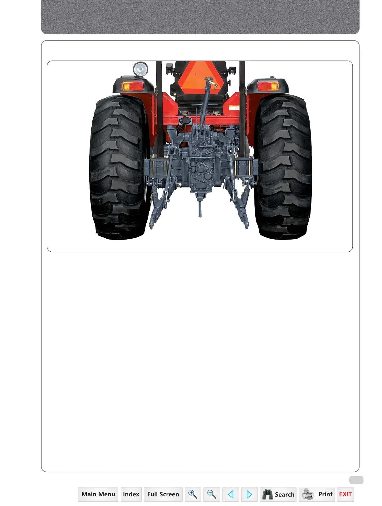
Hydraulics
Thus the only flow
delivered to the cylinder is that controlled by the
lever in use. The inner lever controls the
implement draft and outer lever controls the
implement position. When the spool is in neutral
or hold position the fluid passes through
unloading valve to go to tank. Unloading
When spool is in lift position the part of fluid
passes to the opposite side of unloading valve.
Making unloading valve pressure more than
working pressure. Then the fluid passes through
non return valve to the lift cylinder and rest of
fluid passes through flow control valve to tank.
When spool is in lower position the fluid passes
through unloading valve to tank. The oil trapped
in the cylinder passes through lowering valve to
tank.
1. GENERAL DESCRIPTION
These tractors are equipped with hydraulic system
consist of an engine driven gear pump, lift
housing, connecting pipes and the filter.
The reservoir is transmission housing. The oil used
is common for transmission, hydraulics and
Brakes. A strainer is fitted on transmission.
Addition paper filter is incorporated on suction
line which ensure 100% filteration. Lift housing
houses lift cylinder, control valve, shockload relief
valve, control valve linkages, and Rock shaft.
A pivot bracket in the rear has two holes for
different draft sensitivity, carries a toplink. Heavy
duty top link, collapsible type lower links,
telescopic stabilizer jug & collar lift rods are
provided as part of 3 point linkage.
2. PRINCIPLE OF OPERATION
The direction of oil flow is from strainer, filter,
pump, Auxiliary valves, control valve to lift
cylinder. The lifting of the system is protected
by a relief valve between the pump & control
valve. The cylinder of the system is protected
by shock load relief valve. The control valve is
operated by two levers.
3. HYDRAULIC OPERATION
 Loading...


