I-12
35 Series 4WD, Model - 3535, 4035, 4535 and 5035 SM June’08
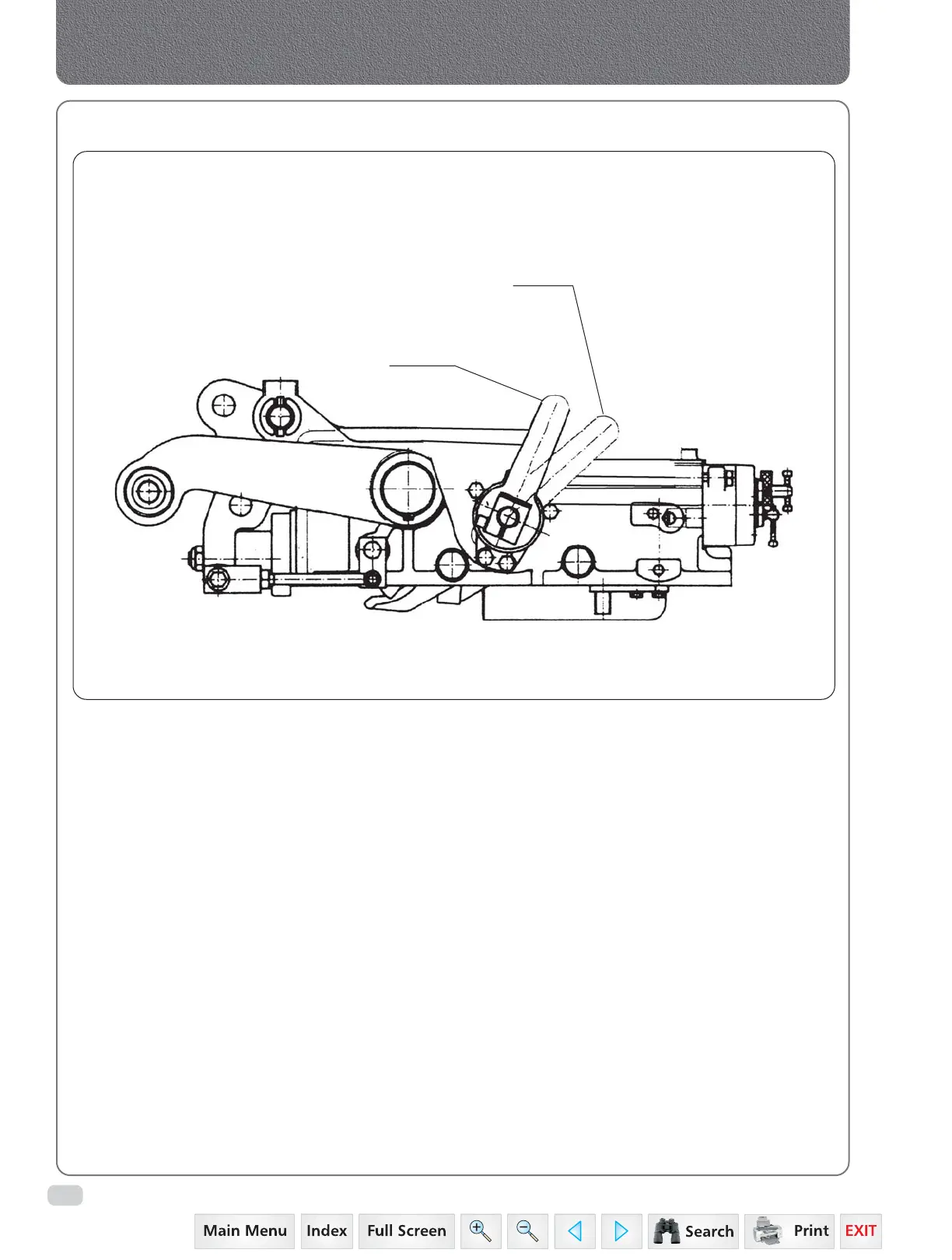
The two control levers carry out following
operations:
A. Position Control
B. Draft Control
C. Combined operation for Position and Draft
Control
The above operations may be chosen in
consideration of the work to be carried out, the
implement type and the soil superficial hardness.
A. POSITION CONTROL (LEVER 1)
Move the draft control lever 2 fully down. Fix
the implement position, inside or outside the soil,
by moving the lever 1 up for raising and down
for lowering.
The implement movement is proportional to the
movement range fixed by means of lever 1.
6. USE OF CONTROL LEVERS
B. DRAFT CONTROL (LEVER 2)
Move the position control lever 1 fully down,
have the implement penetrated into the ground
till reaching the desired depth by gradually
moving the lever 2 down.
The implement depth reached is proportional to
the draft determined by soil hardness. In this
condition the rockshaft keeps the draft required
automatically constant.
Once the draft is regulated at the end of the rope
is possible to lift the implement with position
lever 2 in order to keep in memory the draft.
During last movement stroke of lever 2 a floating
function is obtained and the rockshaft does not
control the draft.
Hydraulics
LEVER 1
LEVER 2
 Loading...


